How to replace lower control arm nissan rogue: DIY Repair Guide
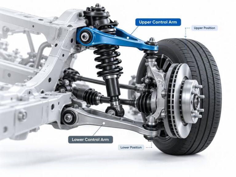
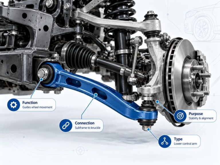
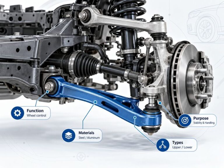
A worn lower control arm can make a Nissan Rogue feel loose, noisy, or unwilling to track straight. You may hear a clunk over bumps, notice uneven tire wear, or feel the vehicle pull while braking. The control arm connects the steering knuckle to the subframe, so its bushings and ball joint have a direct effect on how the front wheel is held in position.
Learning how to replace lower control arm nissan rogue is realistic for a careful home mechanic, but it is not a quick tire-change job. The vehicle must be supported securely, the correct replacement must match the Rogue’s year and drivetrain, and fasteners that use rubber bushings must be tightened with the suspension near normal ride height. A mistake here can affect steering control.
This guide covers identification, safe lifting, removal, installation, tightening, and post-repair checks. It assumes you are replacing a complete control arm assembly rather than pressing in a separate bushing or replacing only a ball joint. Because Nissan Rogue generations and fastener arrangements differ, use the service information for your exact model to confirm torque specifications before final assembly.
At a glance
- Support the Rogue on properly rated jack stands before working underneath it.
- Match the replacement arm to the exact year, engine, drivetrain, and side of the vehicle.
- Have a wheel alignment checked after the repair, especially if the old arm was bent or the steering wheel is no longer centered.
How to replace lower control arm nissan rogue
The safest practical method is to replace one complete front lower control arm at a time, keeping the opposite side assembled for reference. The basic sequence is to confirm the diagnosis, remove the wheel and connected hardware, support the knuckle, detach the arm, install the new part without prematurely tightening its rubber bushings, and torque everything using the specifications for your Rogue.
Tools you will need
- Floor jack and two properly rated jack stands for lifting and supporting the vehicle
- Wheel chocks to prevent movement
- Socket and wrench set, including extensions and a breaker bar for suspension fasteners
- Torque wrench that covers the required tightening range
- Ball-joint separator or suitable puller, if the joint is tapered and stuck
- Penetrating oil and a wire brush for corroded threads
- Replacement lower control arm assembly matched to the exact Rogue application
- Paint marker or scribe for marking positions before removal
- Optional: pry bar, rust penetrant, and a second jack for supporting the steering knuckle

Step 1 Confirm the failed part and obtain the correct replacement
Before lifting the vehicle, inspect the symptoms and compare the replacement arm with the original. A lower control arm commonly fails through a torn bushing, excessive movement at the ball joint, a bent arm, or corrosion around the mounting area. However, a clunk can also come from a sway-bar link, strut mount, tie-rod end, or loose brake hardware.
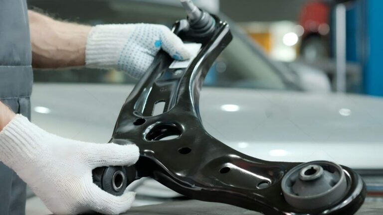
Look up the part by the Rogue’s model year, trim, engine, drivetrain, and front side. Some assemblies include a ball joint and others do not, and left- and right-hand arms are not interchangeable. Compare the new arm’s shape, mounting eyes, ball-joint stud, and included hardware before disassembly.
If the ball joint is loose enough to move by hand, the control arm is visibly bent, or the bushing has separated from its sleeve, replacement is reasonable. Do not begin if you cannot identify the damaged component or if the subframe is badly rusted; a suspension shop can inspect the structure more safely.
Step 2 Prepare the Rogue on level ground
Park on a hard, level surface, select Park in an automatic transmission, set the parking brake, and switch off the ignition. Chock the rear wheels on both sides. If the front wheel uses a locking lug nut, locate the key before lifting the vehicle.
Loosen the front wheel lug nuts slightly while the tire is still on the ground. Do not remove them yet. Read the owner’s manual for the approved jacking point, and never rely on the jack supplied for roadside tire changes as the only support while you work underneath the Rogue.
Important
Never place any part of your body under a vehicle supported only by a floor jack. Lift the Rogue at its approved point, set it on jack stands under sound structural support, and give the vehicle a firm push before starting work.
Step 3 Lift the front corner and remove the wheel
Raise the front of the Rogue high enough to remove the wheel and access the control-arm fasteners. If both front wheels need to be off the ground, support both sides at equal-height stands; otherwise, work on one side while keeping the vehicle stable and level enough for the task.
Place a jack stand under an approved reinforced support point, lower the vehicle onto it slowly, and leave the floor jack lightly positioned as secondary support if it does not interfere. Remove the lug nuts and wheel, then slide the wheel under the vehicle as an additional safeguard rather than treating it as a substitute for jack stands.
Inspect the exposed arm, ball joint, brake hose, ABS wiring, and nearby subframe. Photograph the original routing and hardware orientation. If you see a cracked subframe, a stretched brake hose, or a damaged ABS wire, stop and address that larger problem before installing the arm.
Step 4 Support the steering knuckle and identify the fasteners
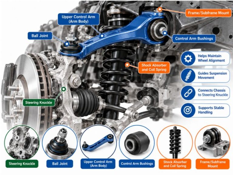
The steering knuckle is the upright part that carries the wheel hub and connects to the suspension. Place a second jack under a strong, non-damaging point of the knuckle or hub assembly, using a wood block only where it cannot crush or distort a component. Apply light support so the knuckle does not drop when the ball joint separates.
Identify the control arm’s front and rear subframe bolts, the ball-joint connection, and any separate stabilizer-bar or bracket hardware attached to the arm on your Rogue. Clean exposed threads with a wire brush and apply penetrating oil to rusty fasteners. Avoid spraying friction surfaces such as the brake rotor or pads.
Mark the original bolt head orientation and note any washers, spacers, or eccentric hardware. Most control-arm mounting bolts are not intended to be adjusted casually, but a mark helps you restore the original arrangement and notice if a special alignment-related fastener is present.
Step 5 Disconnect components that hold the arm in place
Remove any lower splash shield or small bracket that blocks access. If the ABS wire or brake hose is clipped to the control arm, release the clip carefully without pulling the wire or allowing the brake hose to support the knuckle.
Separate the ball joint from the steering knuckle according to the design on your Rogue. Remove the retaining nut only after the knuckle is supported. If the tapered stud does not release with light, controlled force from a proper separator, use a puller rather than hammering directly on the threaded end or the steering knuckle.
Some Rogue versions use a pinch-bolt connection, while others may use a different retention arrangement. Remove only the hardware that secures the ball joint, and keep the separator clear of the rubber boot. A torn boot can contaminate the joint even if the new arm is otherwise installed correctly.
Step 6 Remove the control-arm mounting bolts
With the ball joint detached and the knuckle still supported, remove the control-arm pivot bolts. Start with the more accessible fastener and leave one bolt loosely installed until the arm is ready to come out. This prevents the arm from dropping unexpectedly and gives you control if the bushing is under load.
Use a breaker bar for stubborn bolts, but keep the socket fully seated and work slowly. If a nut spins inside a captured area or a bolt contacts the subframe, stop rather than forcing it. Consult the exact service procedure because some fasteners may require counterholding, a specific removal angle, or access through a nearby opening.
Once the final bolt is removed, lower the arm by hand. Do not let it hang from the ball-joint boot, brake hose, or ABS wire. Compare the removed arm with the new one and transfer only the hardware that the replacement instructions specifically require.
Step 7 Prepare the mounting surfaces and inspect surrounding parts
Clean rust and dirt from the subframe mounting faces with a wire brush. Do not grind away structural metal or enlarge a mounting hole. The new arm should sit flat against its mounting surfaces without trapped debris.
Inspect the removed hardware for damaged threads, stretched bolts, severe corrosion, or a rounded head. Replace single-use or torque-to-yield fasteners when the service information requires it; do not assume every old bolt is reusable simply because it looks intact.
While access is open, check the opposite control arm, sway-bar link, tie-rod end, strut, CV axle boot, and wheel hub for obvious looseness or damage. This is an inspection opportunity, not a reason to replace unrelated parts without a diagnosis.
Step 8 Install the replacement arm loosely
Position the new arm in the same orientation as the original. Start the pivot bolts by hand to prevent cross-threading, but leave them loose enough for the arm to move. If the ball joint has a tapered stud, guide it into the knuckle without forcing it sideways or damaging its boot.
Install the ball-joint nut and any retaining hardware, then reconnect the arm-side brackets or clips. Make sure the brake hose and ABS wire follow their original paths and are not stretched at full steering movement. A replacement arm should sit naturally; if the bolt holes do not align, do not pull the arm into place with the fastener.
Use the support jack to adjust the knuckle height slightly while aligning the ball joint. Keep fingers away from pinch points between the arm, knuckle, and subframe. When all hardware starts smoothly by hand, the arm is positioned correctly enough for final tightening.
Step 9 Set the suspension near ride height before final bushing torque
Rubber control-arm bushings twist as the suspension moves. If you fully tighten a bonded bushing while the arm hangs at full droop, the rubber can be preloaded when the Rogue returns to the ground. That can shorten bushing life and alter the suspension’s normal movement.
Before final torque on the pivot bolts, use the jack under the knuckle or another approved support point to raise the suspension to approximately its normal ride-height position. Do not lift the vehicle off the stands and do not place the jack under a thin sheet-metal component. The arm should resemble its loaded position rather than hanging sharply downward.
Now tighten the pivot bolts, ball-joint fastener, and any related hardware to the exact specifications for your model. A torque wrench is essential here; “tight enough” is not a reliable suspension specification. If the service information gives a tightening sequence, angle, or loaded-height requirement, follow it exactly.
Helpful tip
Do not use an impact wrench for the final tightening of control-arm or ball-joint fasteners. An impact can over-tighten a fastener, damage a bushing, or make it difficult to recognize cross-threading.
Step 10 Reinstall the wheel and lower the vehicle
Check that no tool, jack, or loose hardware remains near the brake rotor. Refit the wheel, thread the lug nuts by hand, and snug them in a crisscross pattern while the vehicle is still supported.
Remove the wheel from beneath the vehicle, raise the Rogue slightly, and take away the jack stand. Lower the vehicle fully and torque the lug nuts in the manufacturer’s specified pattern and range. Recheck that the ball-joint retainer, pivot bolts, clips, and brake or ABS routing are all secure.
Turn the steering wheel from near-left to near-right while watching the repaired area through the wheel opening. Nothing should bind, pull tight, contact the tire, or touch the rotor. If anything moves abnormally, lift the vehicle safely again and find the cause before driving.
Step 11 Perform a controlled initial check and arrange alignment
With the engine off, press the brake pedal several times if the caliper or brake hose was disturbed. The pedal should feel firm. Start the Rogue and listen for unusual noise while turning the steering wheel slightly, but do not use steering movement as a substitute for a road test.
Drive first at low speed in a safe area. Check for clunks, steering pull, vibration, brake-hose interference, and a steering wheel that sits noticeably off-center. Stop immediately if the vehicle wanders, the wheel shakes, the brakes feel abnormal, or a fastener appears loose.
Have a professional shop check the front wheel alignment after the repair. Even when the control arm is installed in its original position, replacing a bent component or disturbing a mounting point can change camber, caster, or toe. An alignment printout gives you a useful record of whether the front wheels are aimed correctly.
What the lower control arm does on a Nissan Rogue
The lower control arm is a strong suspension link between the front subframe and the steering knuckle. Its inner bushings allow controlled movement, while its outer ball joint allows the knuckle to steer and move vertically. Together, these parts help keep the wheel located under the vehicle during acceleration, braking, and bumps.
A failed bushing may show cracking, separation, or movement between the rubber and its metal sleeve. A worn ball joint may produce looseness, a clunk, or uneven tire wear. The same symptoms can come from other suspension parts, which is why checking the actual movement before ordering a control arm matters.
The phrase how to replace lower control arm nissan rogue covers several generations with different hardware and specifications. Treat the model-specific repair manual as the final authority for torque values, lifting points, ball-joint design, and whether a fastener must be replaced.
Complete arm versus separate bushing or ball joint
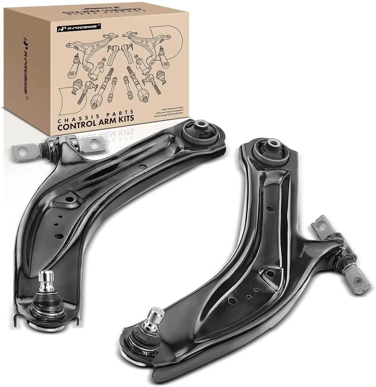
A complete arm assembly is usually the simpler choice for a beginner because the bushing and, where included, ball joint arrive installed. It also avoids the need for a hydraulic press and the risk of installing a pressed component at the wrong depth or orientation.
A separate bushing or ball joint may be appropriate when the original arm is sound and the replacement part is available for that exact application. That repair requires specialized removal and pressing equipment, careful orientation, and additional attention to corrosion. If the arm is bent or its mounting eyes are damaged, replacing only a bushing does not correct the problem.
How to verify the repair
A successful repair is more than a quiet test drive. Confirm the fasteners were tightened with the suspension positioned correctly, the wheel was torqued, and all wires and hoses remain protected throughout steering and suspension travel.

- Compare the completed side with the untouched side for routing and hardware placement.
- Look for a seated ball-joint stud and a properly secured retaining nut or pinch bolt.
- Check that the control-arm bushings are not visibly torn, twisted excessively, or contacting the subframe.
- Turn the steering from lock to lock with the vehicle stationary and listen for contact.
- Check the brake pedal and confirm the ABS warning light does not appear after startup.
- During a slow drive, verify that the vehicle tracks predictably and does not pull sharply.
- Schedule an alignment and inspect the replaced area again after the first normal drive.
Check your result
The repair passes an initial check when the wheel is secure, the steering moves freely, the brake pedal feels normal, there is no hose or tire contact, and the Rogue drives without new clunks or pulling.
Common problems during the repair
Suspension work often becomes difficult because of corrosion or stored spring-like tension in the parts. Do not solve a stuck fastener by applying uncontrolled heat near rubber, brake fluid, wiring, or fuel-related components. If a bolt will not move without risking damage to the subframe, pause and get model-specific repair advice.
| Symptom | Likely area to recheck |
|---|---|
| Clunk remains over bumps | Ball-joint fastener, control-arm pivots, sway-bar link, strut mount, or a different worn component |
| Vehicle pulls or steering wheel is off-center | Alignment, tire pressure, incorrectly seated arm, or a bent suspension part |
| Grinding or rubbing while turning | Brake hose, ABS wire, tire clearance, dust shield, or incorrect arm routing |
| Fastener will not align | Knuckle support height, arm orientation, damaged threads, or the wrong replacement part |
| New bushing looks twisted at rest | Pivot bolts may have been tightened with the suspension hanging |
If the new arm does not fit naturally, compare part numbers and geometry before forcing anything. A wrong side, wrong drivetrain application, or incomplete assembly can look close enough to fool a quick inspection but still change suspension position.
When learning how to replace lower control arm nissan rogue, the most important troubleshooting distinction is between a repair problem and an unrelated fault. If the arm is secure but the Rogue still clunks, inspect the sway-bar links, tie-rod ends, strut mounts, wheel bearing, and brake hardware rather than repeatedly tightening the new part.
Lower control arm replacement FAQs
Can I replace only the lower control arm bushing?
Yes, if the arm itself is straight and the correct replacement bushing is available. Pressing a bushing requires suitable equipment and accurate orientation, so a complete arm is generally more practical for a beginner.
Should I replace both lower control arms at the same time?
Not automatically. Replace the damaged side, then inspect the other side for matching wear, cracks, looseness, or corrosion. Replacing both may make sense when both show similar deterioration, but a sound arm does not need replacement solely because the opposite side failed.
Do I need an alignment after replacing a control arm?
Yes, an alignment check is strongly recommended. Control-arm wear or bending can change wheel angles, and the alignment confirms that the Rogue tracks correctly and will not scrub the tires.
Can I reuse the old control-arm bolts?
Only if the service information permits reuse and the bolts are undamaged. Some suspension fasteners have replacement requirements or special tightening procedures, so verify this for the exact year and configuration.
What if the ball joint will not separate?
Use a suitable ball-joint separator or puller and support the knuckle. Do not hammer directly on the threaded stud or damage the knuckle. If the joint remains stuck or the surrounding metal is heavily corroded, stop and seek professional help.
Finish the repair with a safety check and alignment
Replacing a front lower control arm on a Nissan Rogue is manageable when the vehicle is supported correctly, the exact replacement is confirmed, and the arm is tightened at normal suspension height. The essential habits are controlled disassembly, careful routing of the brake and ABS components, and torque specifications from the correct repair information.
After learning how to replace lower control arm nissan rogue, do not treat the first quiet drive as the final proof. Recheck for contact or looseness, arrange a professional wheel alignment, and stop driving if the Rogue pulls, vibrates, or develops abnormal steering or brake behavior. If the subframe, fasteners, or ball-joint connection are uncertain, handing the vehicle to a qualified technician is the safest next action.