How to Replace Lower Control Arm Nissan Altima: Safe DIY Guide
A worn lower control arm can make a Nissan Altima feel loose, noisy, or unsettled over bumps. You may hear a clunk during braking or turning, notice uneven tire wear, or see the car pull slightly even when the steering wheel appears centered. The arm itself is a strong suspension link, but its rubber bushings and ball joint take a great deal of movement and road impact.
Learning how to replace lower control arm Nissan Altima parts can be manageable for a careful beginner, but it is not a job to rush. The vehicle must be supported securely, the correct replacement part must match the model year and side of the car, and fasteners that locate the suspension need to be tightened correctly.
This guide explains how to identify the arm, prepare the car, remove the old assembly, install the replacement, and check the result. It covers the common front lower control arm arrangement used on many Altima models, while pointing out where year-specific service information matters. If a ball joint is riveted, a bolt is seized, or you cannot support the vehicle safely, stop and use a qualified repair shop.
At a glance
- Confirm the replacement arm matches your Altima’s year, engine, side, and suspension configuration.
- Support the car with rated jack stands and support the steering knuckle before separating the arm.
- Get a four-wheel alignment after the repair, especially if the old bushing was badly worn.
How to replace lower control arm Nissan Altima safely
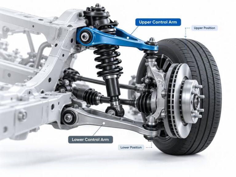
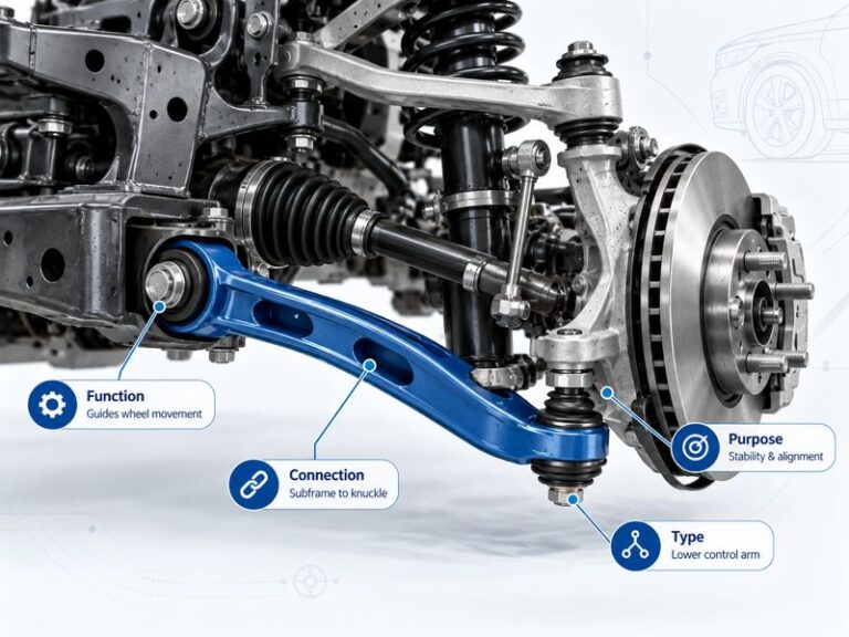
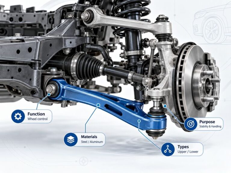
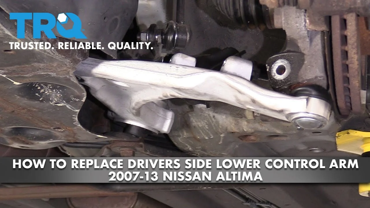
The lower control arm connects the front subframe to the steering knuckle. It controls part of the wheel’s movement while the spring and strut absorb bumps. On many Altimas, the replacement arm includes a new bushing and a ball joint; on some versions, the ball joint may be separate or attached in a way that varies by year.
Verify the exact arrangement before disassembly.
Read the vehicle-specific repair information for torque specifications and suspension details before beginning. The broad procedure below is useful for planning, but it does not replace the factory service manual for your particular Altima.
Tools you will need
- Replacement lower control arm matched to the Altima’s model year and left or right side
- Floor jack and two properly rated jack stands for safely supporting the vehicle
- Wheel chocks to prevent the rear wheels from moving
- Socket and wrench set, including the sizes required for the control-arm fasteners
- Torque wrench for final tightening
- Breaker bar or penetrating oil for stubborn fasteners
- Ball-joint separator, optional if the joint does not release with controlled tapping
- Wire brush and shop light for cleaning and inspecting fasteners and mounting surfaces
Step 1 Confirm the part and inspect the suspension
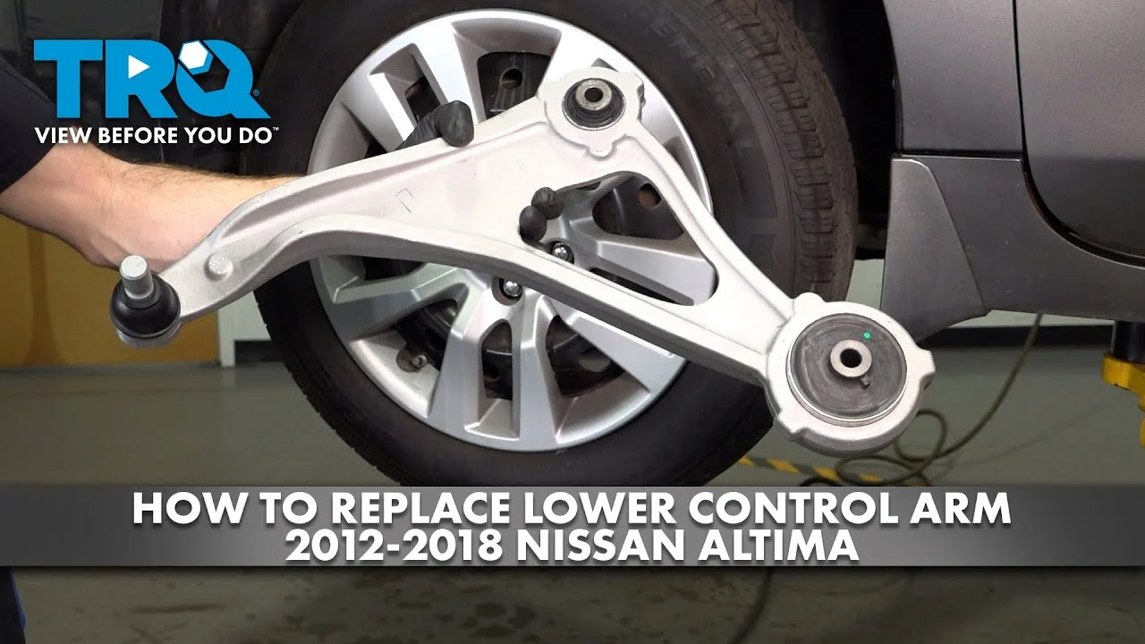
Park on a level, solid surface and compare the new control arm with the one on the car before lifting anything. Check the overall shape, bushing locations, ball-joint stud, mounting holes, and left-versus-right orientation. A part can look close enough while having the wrong bushing position or stud angle.
Look through the wheel opening for obvious damage. A torn bushing, a separated rubber sleeve, or a ball-joint dust boot that is split or leaking grease supports replacement, but a bent steering knuckle, damaged subframe, or cracked spring points to a larger problem. Photograph the installed arm and fastener arrangement if the layout is unfamiliar.
Step 2 Loosen the wheel hardware and lift the front safely
With the car still on the ground, loosen the front wheel lug nuts slightly without removing them. Chock the rear wheels, set the parking brake, and follow the jack-point locations in the owner’s manual. Raise the front at an approved lifting point, then place jack stands under strong structural support points specified for the vehicle.
Lower the jack slowly until the car rests firmly on both stands. Give the body a cautious shake at a solid area to confirm it is stable, and keep the floor jack nearby without relying on it as the only support. Never work beneath a car held only by a hydraulic jack.
Important
Do not proceed if the stands are on an uneven surface, the lift point is uncertain, or the vehicle shifts when tested. Reposition the equipment before removing the wheel.
Step 3 Remove the wheel and support the steering knuckle
Remove the lug nuts and wheel, then place the wheel under the vehicle only as a secondary precaution; it is not a substitute for jack stands. Identify the lower control arm, the inner mounting bolts or pivot bolts, and the outer ball-joint connection at the steering knuckle.
Position the floor jack under a solid part of the steering knuckle or another approved point so the knuckle cannot drop suddenly when the ball joint is separated. Use a block or adapter only if it remains stable and does not damage the component. Do not place the jack under a thin dust shield, brake rotor, or plastic shield.
Step 4 Remove nearby components that block access
Depending on the Altima year and trim, access may require moving a splash shield, unfastening a brake hose bracket, or disconnecting a stabilizer-bar link from the control arm. Remove only what prevents access, and support any brake hose or wiring so it is not stretched, twisted, or allowed to hang from a connector.
Do not disconnect a brake line just to make room. If the stabilizer link has a ball-and-stud connection, hold the stud with the correct counterhold while loosening the nut. Mark the original position of any eccentric washer or alignment-related hardware, but do not assume the marks replace a professional alignment.
Step 5 Soak and loosen the control-arm fasteners
Brush dirt and rust away from the exposed threads and apply penetrating oil to the control-arm fasteners if needed. Let it work while you identify the nut, bolt head, and any captive hardware. Use the correct socket fully seated on the fastener; rounding a suspension bolt can turn a straightforward repair into a difficult extraction.
Loosen the inner pivot bolts and the outer ball-joint nut, but leave each nut threaded on a few turns until the joint or arm is supported. This keeps the parts from dropping unexpectedly and helps prevent damage to the threads. If a bolt spins with its nut, hold the bolt head or captive nut as the design requires.
Step 6 Separate the ball joint from the steering knuckle
Remove the ball-joint nut after confirming the steering knuckle is supported. Use a ball-joint separator if necessary, selecting a tool that does not tear the dust boot or load the brake hose. On some joints, firm controlled strikes to the side of the steering-knuckle boss can release the tapered stud, but do not hammer directly on the threaded stud or the aluminum control arm.
A useful way to approach how to replace lower control arm nissan altima is to check your progress after each stage.
When the taper releases, the knuckle should remain supported and the control arm should move independently. If the joint will not separate, the tool begins slipping, or the knuckle starts moving toward the brake hose, stop and reset the support. Do not use a torch near rubber boots, brake components, fuel lines, or wiring.
Step 7 Remove the old lower control arm
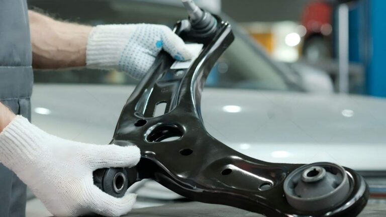
Take out the inner mounting bolts while supporting the arm by hand or with the jack. Lower the arm carefully and guide the ball-joint stud out of the knuckle. Compare the old and new arms on the workbench, checking the bushing orientation, mounting width, stud taper, and any included spacers or hardware.
Inspect the removed hardware. A stretched, badly corroded, damaged, or torque-to-yield fastener should be replaced according to the vehicle’s service information rather than reused automatically. Also inspect the subframe mounting holes and the steering-knuckle taper for cracks, heavy corrosion, or deformation.
Step 8 Position the replacement arm and start every fastener by hand
Guide the new arm into the original position without forcing it sideways. Start the inner bolts and nuts by hand, then place the ball-joint stud into the steering knuckle. If the replacement includes a new nut or cotter pin, use those supplied parts when appropriate; never reuse a damaged locking nut or a bent cotter pin.
Keep the inner pivot fasteners loose enough for the arm to move until the outer connection is installed. This prevents cross-threading and gives the bushings room to settle into position. If the holes do not line up, adjust the supporting jack slightly rather than prying aggressively against the new bushing.
Step 9 Tighten the joints to the vehicle-specific specifications
Run the fasteners down evenly, then torque them with a calibrated torque wrench using the specifications for your exact Altima. Tighten the ball-joint nut and install a new cotter pin if the design uses one. If the nut’s slots do not align with the hole after reaching the specified torque, continue only as directed by the service information; do not loosen it to create alignment.
Pay special attention to the inner pivot bolts. Rubber control-arm bushings are designed to rest near their normal ride height, so tightening them while the suspension hangs can preload the rubber and shorten bushing life. Many vehicles require final tightening with the control arm raised to approximate ride height.
Confirm the required method for your model before applying final torque.
Helpful tip
Write down each final torque value from the correct service source before tightening. “Tight enough” is not a reliable setting for a suspension joint, and a generic torque chart may not match your Altima.
Step 10 Reinstall removed parts and the wheel
Reattach any stabilizer link, brake-hose bracket, splash shield, or wiring clip that was moved. Check that the brake hose is not twisted and that the wheel-speed sensor wire follows its original route. Make sure no tool, rag, or loose hardware remains near the rotor or axle.
Install the wheel and tighten the lug nuts in a star pattern by hand first. Lower the vehicle until the tire touches the ground enough to prevent rotation, then tighten the lug nuts to the vehicle’s specified wheel torque. Fully lower the car and remove the stands and chocks only when it is safe to do so.
Step 11 Settle the suspension and perform a stationary check
Before driving, bounce the front of the car gently several times or roll it a short distance on the level surface so the suspension settles. Turn the steering from side to side while watching for interference, and check that the control arm, ball-joint boot, brake hose, and wheel-speed sensor wire remain clear.
Look beneath the car for a missing nut, a bolt that has backed out, or a bushing that is visibly twisted in an abnormal way. Compare the repaired side with the other side. The vehicle should sit at a normal, even ride height; a dramatic difference suggests a wrong part, a spring problem, or an assembly issue.
Step 12 Complete a cautious road check and arrange alignment
Start with a slow drive in a safe area. Listen for clunks, grinding, or rubbing, and check whether the steering wheel returns normally after a gentle turn. Test braking lightly before normal traffic, because a suspension repair can reveal a loose component or an alignment change.
Do not treat a quiet first drive as proof that the repair is complete. Have the front alignment checked, and request a four-wheel alignment when recommended by the shop or vehicle specification. A control-arm replacement can change toe, camber, or caster enough to affect tire wear and handling even when the steering initially feels acceptable.
Understanding how to replace lower control arm nissan altima also means recognizing the limits of the method.
What the lower control arm does and when replacement is needed
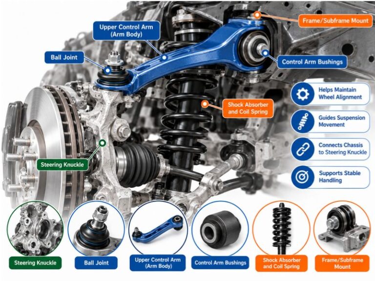
The lower control arm is a hinged link between the subframe and steering knuckle. Its inner bushings permit controlled movement, while the outer ball joint allows the knuckle to steer and travel with the suspension. Together, these parts help keep the wheel positioned under the car.
A worn arm does not always make the car unsafe immediately, but looseness can worsen quickly and affect braking stability. Replacement is more persuasive when inspection shows measurable play, a separated bushing, a damaged ball-joint boot with contamination, or impact damage that has bent the arm.
Symptoms that can point to a worn arm
- A clunk over small bumps or when changing from braking to acceleration
- Steering pull, wandering, or a steering wheel that no longer sits straight
- Uneven or accelerated front-tire wear
- Visible cracking or separation in the control-arm bushing
- Movement at the ball joint during a proper suspension inspection
- Instability after striking a pothole or curb
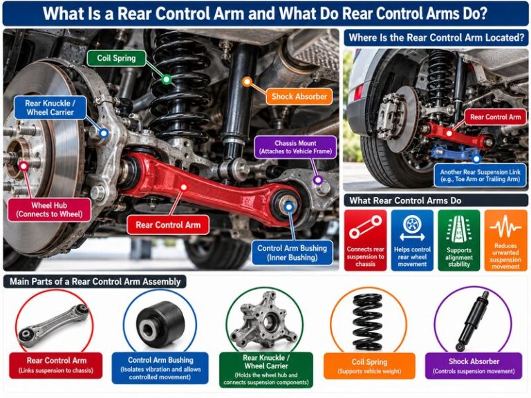
These symptoms are not exclusive to the control arm. A worn tie-rod end, strut mount, stabilizer link, wheel bearing, bent wheel, or incorrect tire pressure can feel similar. Diagnose the whole front suspension rather than replacing a part based only on a noise.
Replace one side or both?
Replace the failed side when the opposite side is in good condition and the diagnosis is clear. Replacing both sides can be sensible when the arms have similar mileage and both bushings are cracked, but it is not automatically required.
If both arms are replaced, compare them before installation and keep track of which fasteners belong to each side. The alignment requirement remains the same, and replacing both does not eliminate the need to inspect tie rods, ball joints, struts, and wheel bearings.
How to verify the repair before normal driving
The best result is not simply a new-looking part. The arm must be installed in the correct direction, all related components must be secured, the wheel must be torqued, and the vehicle must track and steer normally. A final inspection is especially important if the old hardware was rusty or the ball joint required force to separate.
Use this final inspection checklist
- Both inner control-arm fasteners are present and torqued correctly.
- The ball-joint nut is fully seated, with its retaining method installed.
- The brake hose and wheel-speed sensor wire are clipped into their original locations.
- The stabilizer link and any moved splash shield are secure.
- The lug nuts are tightened to the specified wheel torque.
- No tool, loose wire, or suspension part contacts the tire or rotor.
- The vehicle has no immediate fluid leak or visibly displaced component.
- The steering wheel and road behavior are checked at low speed before faster driving.
Check your result
After the short road check, park on level ground and recheck for new looseness, abnormal tire contact, or a fresh clunk. Schedule the alignment promptly rather than waiting for uneven tread wear to appear.
Common problems during lower control arm replacement
Most difficult repairs become difficult because a fastener is seized, the knuckle is not supported, or the replacement part is not an exact match. Work slowly and avoid turning a stuck suspension joint into a damaged brake, sensor, or subframe component.
| What you observe | Likely direction |
|---|---|
| The new arm will not line up | Check side and model compatibility, support height, bushing orientation, and whether another component is still loaded. |
| The ball joint will not release | Use a suitable separator and keep the knuckle supported; stop if the brake hose or sensor wire is being pulled. |
| A clunk remains after installation | Recheck ball-joint and pivot torque, stabilizer links, strut hardware, tie-rod ends, and wheel-lug torque. |
| The car pulls or the wheel is crooked | Check tire pressure and arrange an alignment; inspect for a bent part if the change followed an impact. |
When a seized fastener needs professional help
Surface rust is often manageable with penetrating oil, cleaning, and the correct breaker bar. Stop if the bolt begins twisting, the captive nut breaks loose inside the subframe, or heat would be needed near rubber, fuel, brake, or electrical components without proper protection.
A professional shop has safer ways to support the vehicle and remove damaged hardware. Continuing with improvised leverage can damage the subframe or leave a suspension fastener improperly secured.
When not to drive after the repair
Do not drive normally if the steering feels loose, the car pulls sharply, a wheel rubs, the brake pedal feels abnormal, or a clunk occurs with every movement. Also stop if a cotter pin, locking nut, or control-arm fastener is missing.
Recheck the assembly while the car is safely supported, or have it towed for inspection. A short distance to a repair shop is not automatically safe when a suspension joint may be loose.
Frequently asked questions
These answers address common beginner concerns, but the exact fasteners and torque procedure still depend on the Altima’s model year and suspension configuration.
Can I replace only the lower control-arm bushing?
Sometimes, but pressing a bushing out and installing a new one requires suitable press equipment and correct orientation. Replacing the complete arm is often more practical when the ball joint is also worn or the arm is bent, but use the repair method specified for your exact part.
Do I need an alignment after replacing a lower control arm?
Yes, an alignment check is strongly recommended. Removing and reinstalling the arm can alter wheel geometry, and an alignment is the only dependable way to confirm toe and other settings are within specification.
Can I reuse the old control-arm bolts and nuts?
Reuse them only if the vehicle’s service information allows it and the hardware is undamaged. Replace stretched, deformed, badly corroded, or specified one-time-use fasteners, and use the correct locking nut or cotter-pin arrangement.
Why must some control-arm bolts be tightened at ride height?
The rubber bushing is bonded to its inner sleeve. Tightening it with the suspension hanging can twist the rubber when the car is lowered, which may reduce bushing life and change how the suspension moves.
Is a ball-joint separator required?
Not always, but it is the controlled choice when the tapered stud is stuck. Avoid methods that damage the dust boot, threads, brake hose, or steering knuckle, and stop if the joint cannot be separated safely.
Finish the repair with an inspection and alignment
Knowing how to replace lower control arm Nissan Altima parts is useful when the arm or its attached bushing and ball joint are clearly worn, but safe support and correct torque matter more than speed. Match the part carefully, protect the brake and sensor wiring, support the steering knuckle, and follow the model-specific tightening procedure.
After the car is reassembled, perform a slow road check and arrange a professional alignment. If the vehicle still clunks, pulls, rubs, or feels unstable, stop driving and have the complete front suspension inspected rather than assuming the new control arm solved every problem.