How to Replace Upper Control Arm Bushings Chevrolet S10 at Home
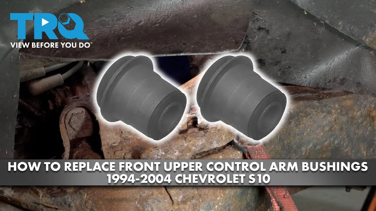
Worn upper control arm bushings can make a Chevrolet S10 feel loose, wander over bumps, or produce a dull clunk from the front suspension. The bushings are rubber sleeves around the control arm’s pivot shaft, and they isolate normal suspension movement while keeping the arm located in a predictable position. When the rubber cracks, separates, or compresses, the truck can lose both ride quality and alignment stability.
Replacing them is a realistic home repair for a careful beginner, but it is not simply a matter of unbolting the arm and installing new rubber. The front suspension may contain a coil spring or torsion bar under substantial stored energy, and the new bushings usually need to be pressed into place. A shop press or a suitable control-arm bushing service tool is safer than hammering them out.
This guide explains how to replace upper control arm bushings Chevrolet S10 models use, while accounting for differences between model years, two-wheel drive and four-wheel drive versions, and original versus replacement control arms. You will learn how to identify the correct parts, preserve alignment shims, remove the arm safely, install the bushings in the correct position, and check the finished repair before driving normally.
At a glance
- Support the truck by the frame and control the coil spring or torsion-bar load before loosening suspension parts.
- Record every alignment shim and press the new bushings in squarely rather than striking the control arm.
- Have the front end aligned after the repair, even if the truck appears to drive straight.
How to replace upper control arm bushings Chevrolet S10 safely
The overall method is to remove one upper control arm, separate the old bushings from the arm and pivot shaft, press in the matching replacements, and reinstall the arm with its original alignment shims. Work on one side at a time so the untouched side remains a useful reference, but do not assume the two sides have identical shim stacks.
Before beginning, identify the truck by model year, drive system, engine, and suspension type. Chevrolet S10 parts catalogs can list different bushings for different applications, and some replacement control arms arrive with bushings already installed. If the new parts do not match the original bushing width, sleeve, pivot shaft, and control-arm mounting arrangement, stop and verify the application before disassembly.
Tools you will need
- Floor jack and four jack stands rated for the truck, used to lift and support the frame securely
- Wheel chocks and basic hand tools, including sockets, wrenches, breaker bar, and torque wrench
- Ball-joint separator or suitable removal tool
- Shop press with correctly sized receiving cups, or a control-arm bushing service kit
- Penetrating oil, wire brush, paint marker, and a container for alignment shims
- Replacement upper control arm bushings matched to the exact S10 application
- Optional: digital angle finder or phone-level application for recording the original arm position
Step 1 Confirm the suspension and inspect the replacement parts
Park on a hard, level surface, set the parking brake, and place chocks behind the rear wheels. Compare the new bushings with the parts on the truck before lifting it. Check the outer diameter, inner sleeve, width, and any supplied washers or sleeves; a close visual resemblance is not enough.
Look at the existing upper control arm and pivot shaft. If the shaft is deeply grooved where the bushings ride, badly bent, or heavily corroded, replacing only the rubber may not produce a durable repair. A damaged shaft or control arm should be replaced or professionally evaluated.
Important
Do not loosen the upper control arm, lower control arm, spring retainers, or torsion-bar hardware until you understand how your particular S10 stores spring energy. If the procedure in the factory service information calls for a spring compressor or torsion-bar unloading tool and you do not have the correct equipment, stop and use a qualified repair facility.
Step 2 Lift the truck and remove the wheel
Break the wheel lug nuts loose slightly while the tire is still on the ground. Position the floor jack under a manufacturer-approved lifting point, raise the front of the truck, and place jack stands under solid frame locations. Lower the truck gently onto the stands, then shake the body lightly to confirm it is stable before removing the wheel.
Keep the jack available under the lower control arm only as a controlled support if the service procedure calls for it; never use a jack as the sole support for a vehicle. The frame should rest on the stands, and the suspension should remain arranged in a way that does not release a spring unexpectedly.
Step 3 Record alignment shims and expose the upper arm hardware
Clean the area around the upper control arm pivot bolts and the frame brackets. Use a paint marker to mark the relationship between the alignment washers or shims and the frame, then photograph both sides. Remove each shim carefully and place the shims from the front and rear pivot locations in separate labeled containers.
These shims adjust camber and caster. They are not merely spacers, and putting them back in the wrong location can change wheel alignment enough to cause tire wear or unstable handling. The marks are only a reference because the truck still needs a professional alignment after reassembly.
Step 4 Disconnect components that hold the arm in place
Remove any brake hose bracket, ABS wire bracket, sway-bar link, or other attachment that prevents the upper arm from moving. Do not allow a brake hose or electrical wire to hang from the control arm. Support the steering knuckle as needed so it does not pull on the brake line when the upper ball joint is separated.
Remove the cotter pin from the upper ball-joint stud and loosen the nut, leaving it threaded on a few turns. Use a ball-joint separator on the joint or strike the side of the steering-knuckle boss with a proper hammer while keeping the stud and boot protected. Do not hammer directly on the threaded stud or pry against the rubber boot.
When the taper releases, remove the nut and support the knuckle independently. If the joint will not separate with reasonable force, use a better-fitting separator rather than escalating to uncontrolled blows. A torn ball-joint boot or damaged stud is a reason to replace the joint before continuing.
Step 5 Remove the upper control arm without losing the spring load
Remove the nuts or bolts securing the upper control arm pivot shaft to the frame, keeping track of the shim locations. Withdraw the arm only after confirming that the spring or torsion-bar load is controlled according to the truck’s suspension design.
On a coil-spring S10, the spring may be positioned between the lower control arm and the frame, but its movement can still affect the suspension when the ball joints or control arms are separated. On torsion-bar-equipped models, do not remove or loosen torsion-bar components casually; the bar must be unloaded with the specified procedure and tool if the repair requires it.
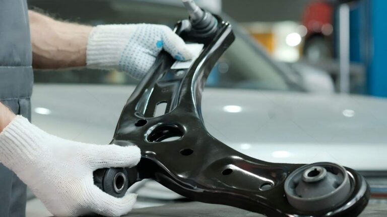
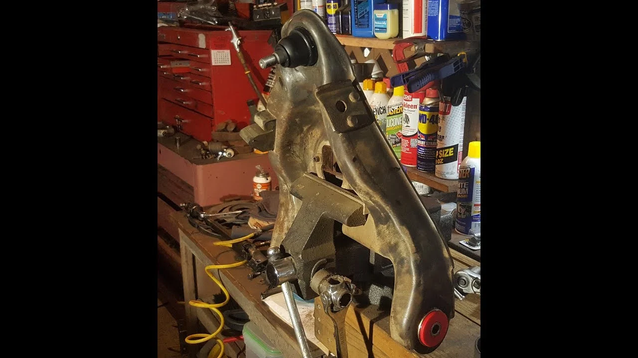
Once the arm is free, keep the pivot shaft, washers, nuts, and shims together. Lay the arm on a sturdy workbench and compare its orientation with the new bushings. The bushing flanges, sleeves, and offset—if present—must face the same way as the original design.
A useful way to approach how to replace upper control arm bushings chevrolet s10 is to check your progress after each stage.
Step 6 Remove the old bushings with a press
Clean dirt and rust from the control arm and pivot shaft. Before pressing anything, study how the original bushings are installed: note which flange faces outward, how far each bushing protrudes, and whether the inner sleeve is centered or offset.
Use a shop press and cups that support the control arm around the bushing while allowing the bushing to pass through. Press on the bushing shell or sleeve as appropriate for the tool setup, never on a thin part of the control arm. Keep the arm square to the press ram so the bushing does not cock and deform the arm.
If the old rubber is bonded tightly to the pivot shaft, follow the replacement manufacturer’s instructions. Some designs require removing the inner sleeve and rubber before pressing out the outer shell. Do not heat the arm with a torch near rubber, paint, grease, or unknown coatings, and do not grind into the control-arm bore.
Helpful tip
Take a measurement from the control-arm edge to the old bushing flange before removal if the design provides a clear reference. Use it only as an installation guide; the new bushing must ultimately seat against its designed stop, not merely match a guessed measurement.
Step 7 Clean the bores and prepare the new bushings
Inspect the control-arm bores after the old bushings are out. Remove rust, rubber residue, and burrs with a wire brush or fine abrasive, then wipe the surfaces clean. The bore should be smooth and round, without cracks, elongated holes, or raised metal that would prevent the new bushing from seating.
Compare each replacement bushing with the removed part again. If the bushing has an arrow, offset, chamfer, or different flange thickness, orient it according to the vehicle or bushing manufacturer’s instructions. Use only the lubricant specified for the bushing material; petroleum grease can damage some rubber, while certain replacement bushings are intended to be installed dry.
Step 8 Press the new bushings into the control arm
Set the control arm and receiving cups in the press so the force is centered on the bushing. Press slowly and check the alignment after each small movement. The bushing should enter straight, with the flange remaining even around the arm rather than angled on one side.
Stop when the flange or shell reaches the designed seat. Do not continue pressing simply because more force is available. Over-pressing can distort the bushing, collapse its sleeve, or deform the control arm.
Install the pivot shaft and any washers in the same order used originally, unless the replacement instructions specify a different sequence.
Some factory-style rubber bushings are tightened only after the suspension is at normal ride height so the rubber is not twisted at rest. Follow the service instructions for the specific bushing and fastener design. If the bushing uses a bonded rubber sleeve, final tightening at the wrong suspension height can shorten its life.
Step 9 Reinstall the control arm and reconnect the ball joint
Position the rebuilt upper control arm in the frame brackets and reinstall the pivot hardware with the original shim groups in their marked locations. Start all fasteners by hand so the shaft does not cross-thread and the shims remain aligned.
Reconnect the upper ball joint to the steering knuckle and install the nut. Use a new cotter pin wherever the design uses a castellated nut and cotter pin; never reuse a damaged or previously bent pin. Reattach brake-line and ABS-wire brackets exactly as they were routed, leaving enough slack for steering and suspension travel but no possibility of rubbing the tire.
Do not fully torque rubber-bushing pivot fasteners while the control arm hangs far below normal ride height unless the manufacturer specifically permits it. Support the suspension at approximate ride height with the jack, while keeping the frame safely supported, and then perform the final torque procedure specified for the truck.
Step 10 Torque the fasteners and reinstall the wheel
Use a reliable torque wrench and the torque values for the exact year and suspension configuration. Tighten pivot fasteners, ball-joint hardware, wheel nuts, and any bracket fasteners according to the service information. Torque values can differ between model years and between standard and heavy-duty suspension parts, so do not substitute a generic S10 number.
Check that the steering knuckle turns freely from side to side and that the brake hose and ABS wire do not stretch, kink, or contact the tire. Reinstall the wheel, tighten the lug nuts in a star pattern, raise the truck slightly, remove the stands, and lower it fully before final wheel-lug torque.
Step 11 Settle the suspension and perform the initial inspection
Before driving, bounce the front of the truck several times and roll it a short distance on the driveway so the suspension settles. Turn the steering from lock to lock while watching for interference. Look for a bushing flange that has shifted, a loose shim, a missing fastener, or a brake hose that changes position sharply.
Understanding how to replace upper control arm bushings chevrolet s10 also means recognizing the limits of the method.
Verify that both front wheels sit normally in the wheel openings and that the truck does not lean unexpectedly. A small difference in appearance can come from the ground or tire pressure, but a sudden lean, binding control arm, or metallic snap means the repair should not be driven until the cause is found.
What the upper control arm bushings do on an S10
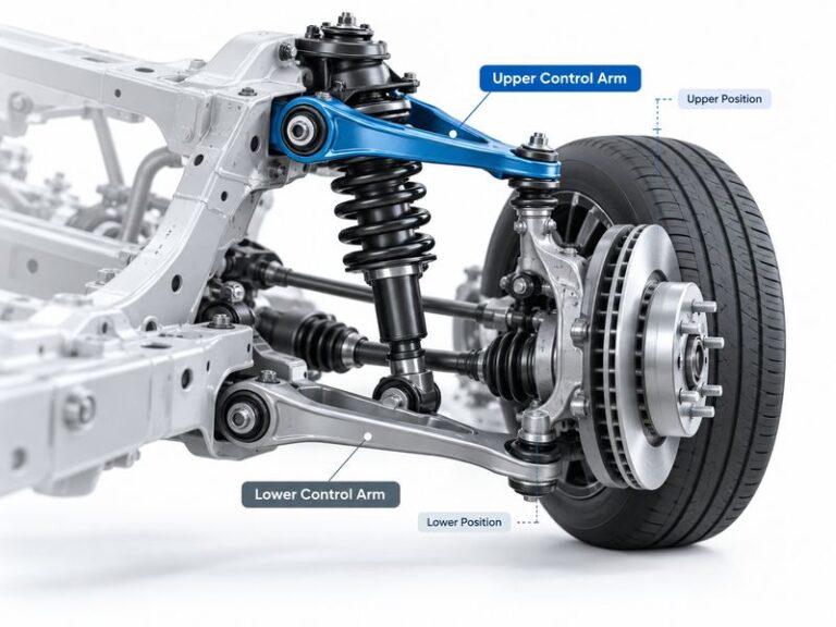
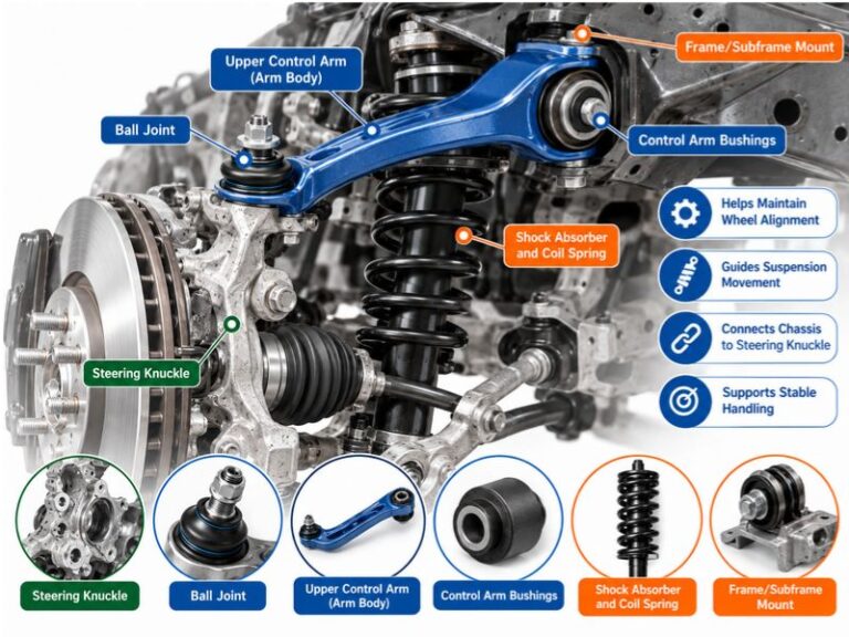
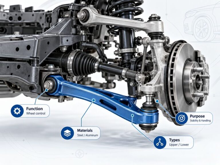
The upper control arm connects the frame to the steering knuckle and helps control the wheel’s camber as the suspension moves. Its bushings allow the arm to pivot without metal-to-metal contact while limiting unwanted fore-and-aft movement.
Symptoms of worn bushings can overlap with symptoms from a bad ball joint, tie-rod end, wheel bearing, bent wheel, or incorrect alignment. A visible crack in rubber is not automatically proof that the bushing is the only problem. Excessive movement while an assistant turns the steering wheel or moves the suspension is more useful than appearance alone.
When the bushings are not the real problem
Inspect the upper and lower ball joints, tie-rod ends, idler arm, pitman arm, wheel bearings, shocks, leaf-spring mounts, and tire condition while the truck is raised. Check for looseness only with the correct suspension unloaded or loaded position, because some joints can appear tight in one position and loose in another.
If the control-arm pivot shaft is worn where it passes through the bushings, new rubber alone may leave play. Likewise, a damaged frame bracket can prevent proper alignment. These conditions should be corrected before an alignment is attempted.
How to check the completed repair
A successful repair is quiet, secure, and followed by a proper alignment. The original shim arrangement helps the truck return close to its previous setting, but removing and reinstalling a control arm can still alter camber and caster. Schedule a four-wheel alignment or the alignment service appropriate for the S10’s rear suspension.
Ask for an alignment printout if available. The important result is not that every number matches a generic target, but that the settings fall within the vehicle-specific specification and are reasonably balanced from side to side. The technician should also inspect for bent components or seized adjusters if the readings cannot be corrected.
Use a gradual road test
Start at low speed in an empty area. Listen for clunks during braking, acceleration, steering input, and small bumps. The steering wheel should return normally, and the truck should not pull strongly to either side on a reasonably level road.
After a short drive, park safely and recheck the visible hardware, wheel-lug torque, brake-hose routing, and bushing position. Recheck again after the first normal drive if the service information or bushing manufacturer recommends a fastener inspection.
Check your result
The repair is ready for normal use only when the fasteners are correctly torqued, the suspension moves without binding, no brake or ABS wiring is strained, and an alignment confirms safe geometry.
Common problems during the repair
Most difficulties come from incorrect parts, lost alignment shims, poor press support, or an uncontrolled suspension component. The table below helps separate a correctable assembly issue from a reason to stop.
| Observation | Likely cause and response |
|---|---|
| New bushing enters crooked | Press setup is not square or the bore has a burr. Stop, realign the cups, and inspect the bore before continuing. |
| Pivot shaft will not pass through | The bushing sleeve is misaligned, the wrong bushing is installed, or the shaft is bent or corroded. Do not force it with the pivot bolt. |
| Truck pulls after repair | Alignment changed, a shim was misplaced, or another steering or suspension part is worn. Obtain an alignment and inspect the front end. |
| Clunk remains | Check ball joints, tie-rod ends, wheel bearings, sway-bar links, shock mounts, and loose hardware instead of assuming the new bushings failed. |
| Control arm binds during movement | Rubber may have been tightened at the wrong height, the bushing may be over-pressed, or the arm may be bent. Stop driving until corrected. |
When to stop and get professional help
Stop if the spring or torsion bar cannot be safely controlled, a press begins to tilt, the control arm cracks, a frame bracket moves, or a ball-joint stud spins instead of tightening. Also stop if you cannot identify the correct shim arrangement or torque specifications.
Front suspension parts affect steering and braking. A repair that is nearly correct is not safe enough, so use a professional suspension shop when the required equipment or service information is unavailable.
Frequently asked questions
Can I replace the upper control arm instead of pressing in bushings?
Yes, if a complete replacement arm is correctly matched to the S10 and includes properly installed bushings. Compare the new arm with the original, transfer the alignment shims carefully, and still obtain an alignment afterward.
Do I need to replace the upper ball joint at the same time?
Not automatically. Replace it if the joint has measurable looseness, a damaged boot, corrosion, or fails the applicable inspection. Since the joint is already separated, this is a practical time to replace a worn joint, but a sound joint does not need replacement solely because the bushings are being serviced.
Can I use a hammer instead of a press?
A hammer is a poor choice for pressing control-arm bushings because it can bend the arm, damage the bore, or send metal fragments outward. Use a shop press or a purpose-built bushing service tool, or have a machine or suspension shop perform the pressing.
Why must I keep the alignment shims?
The shims set the control arm’s position relative to the frame and therefore affect camber and caster. Losing or swapping them can create a large alignment change, although preserving them does not eliminate the need for a final alignment.
How can I tell whether my S10 uses coil springs or torsion bars?
Look underneath the front suspension or consult the exact vehicle service information. A torsion-bar system has a long torsion bar running rearward from the lower control-arm area, while a coil-spring version has a helical spring. Do not rely only on a general S10 parts listing because drive system and model year matter.
Finish the repair with an alignment and safety check
Learning how to replace upper control arm bushings Chevrolet S10 models use comes down to controlling suspension energy, preserving the alignment shim layout, pressing the bushings squarely, and tightening the hardware at the correct suspension position. The visible repair is complete only after the arm moves freely, all brackets and lines are secure, and the fasteners are torqued to the correct specification.
Take the truck for a professional alignment before treating it as finished. If the truck still pulls, clunks, binds, or shows uneven tire contact afterward, stop driving it and have the entire front suspension inspected rather than assuming the new bushings are the cause.