How to Remove a Ball Joint From a Control Arm: Practical Guide
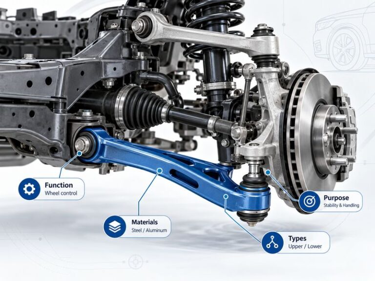
A worn ball joint can cause clunking, wandering, uneven tire wear, or play in the steering, but removing it is not usually a matter of simply turning a wrench. The joint is commonly pressed tightly into the control arm, and some factory-installed versions are secured with rivets instead of a removable snap ring. The suspension may also store dangerous spring force, so the order of the work matters.
This guide explains how to remove a ball joint from a control arm after the control arm has been safely removed from the vehicle. It covers the common press-in design, the differences between a snap-ring joint and a riveted joint, and the checks that tell you whether the arm is ready for a replacement. A vehicle-specific service manual is still necessary for lifting points, torque specifications, and any spring-removal procedure.
The realistic beginner-friendly method is to use a purpose-built ball joint press or a properly sized hydraulic press. A hammer may help remove a corroded snap ring or knock off rivet heads, but it should not be the main method for driving the joint out while the control arm is unsupported. If the arm is badly cracked, bent, or too corroded to support safely, replacement or professional service is the safer answer.
At a glance
- Remove the control arm before pressing out its ball joint unless the vehicle manual specifies another method.
- Support the control arm close to the joint and keep the press cups aligned so the arm is not bent.
- Confirm the replacement joint matches the arm and verify that the bore is round, clean, and undamaged.
How to remove a ball joint from a control arm safely
The procedure below assumes the control arm is already off the vehicle and on a stable work surface. If it is still installed, stop here and follow the vehicle-specific removal procedure first; disconnecting a control arm can release spring tension or allow the steering knuckle to move unexpectedly.
Tools you will need
- Ball joint press kit with correctly sized receiving cups and adapters
- Bench vise or sturdy workbench to hold the control arm securely
- Socket set, ratchet, and breaker bar for the joint hardware
- Snap-ring pliers for a joint retained by a snap ring
- Wire brush, penetrating oil, and shop rags for cleaning the bore and hardware
- Eye protection and mechanic’s gloves; use hearing protection when cutting or striking metal
- Optional: angle grinder or air chisel for removing rivet heads when the joint is riveted
- Optional: hydraulic press with properly sized plates and support blocks
Step 1 Confirm the replacement joint and identify how the old one is retained
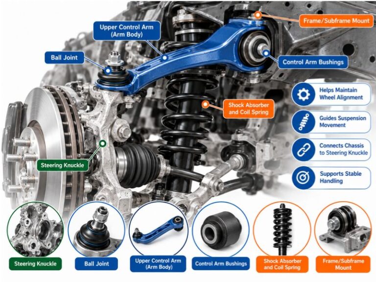
Before applying force, compare the new ball joint with the control arm and the old joint. Check the stud diameter and taper, housing diameter, snap-ring groove, mounting-hole pattern, and grease-fitting position. A joint can look similar while having the wrong taper or press fit, so do not rely on appearance alone.
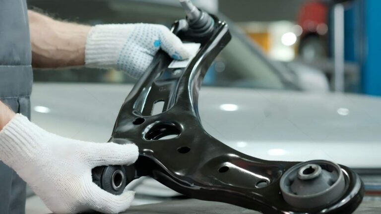
Look at the joint from the underside and top of the control arm. A removable joint usually has a snap ring, circlip, flange, or retaining ring around the housing. A factory-installed riveted joint has a flange held by several rivets, while a bolted service joint has nuts or bolts that must be removed before pressing.
Read the vehicle service information for the correct control-arm orientation and any special adapter requirement. Some ball joints are designed to press in or out only from one side. The larger shoulder or flange generally indicates the side where the joint seats, but the old part and the service manual are better guides than a guess.
Step 2 Secure the control arm and make the joint accessible
Place the control arm on a sturdy bench or in a large vise with the joint facing upward or downward according to the removal direction. Support the arm on broad, solid areas close to the ball-joint housing, not on thin edges, bushings, or unsupported sheet metal. The supports must leave a clear path for the joint to move out.
Keep the arm level. If it rocks when you push on it by hand, it is not supported well enough for a press. A moving arm can let an adapter slip, damage the bore, or eject a cup with considerable force.
Take a photograph or make a paint mark showing the joint’s orientation before removal. This is especially useful when the joint has an offset housing, an angled grease fitting, or a flange that can be installed in more than one position.
Important
Do not clamp a control arm directly across a delicate stamped section or use a jack as the only support. Keep your hands away from the press path, wear eye protection, and never stand over a loaded press or hammering setup.
Step 3 Remove the retaining ring or service hardware
If the joint has a snap ring, remove dirt and rust from the groove first. Apply penetrating oil and use snap-ring pliers that fully engage the ring holes. Shield the ring with a rag as it comes out; a rusted ring can spring free unexpectedly.
Some retaining rings have one beveled side, an open end, or a small access notch. Note how the ring was installed, then set it aside if it will be reused only when the manufacturer permits reuse. Many replacement joints include a new ring, and a distorted or heavily rusted ring should not go back into service.
For a bolted joint, remove the nuts and bolts while the arm remains firmly supported. If the fasteners are seized, avoid twisting the control arm or heating a part near a rubber bushing unless the service instructions allow it. Replace damaged hardware with the correct grade and specification rather than substituting ordinary bolts.
If the joint is riveted, do not try to press it out while the rivet heads still hold the flange. Mark the joint’s position, then remove the rivet heads with an angle grinder or air chisel. Grind only until the head separates from the flange; cutting deeply into the control arm can weaken the mounting surface.
Step 4 Set up the press cups in the removal direction
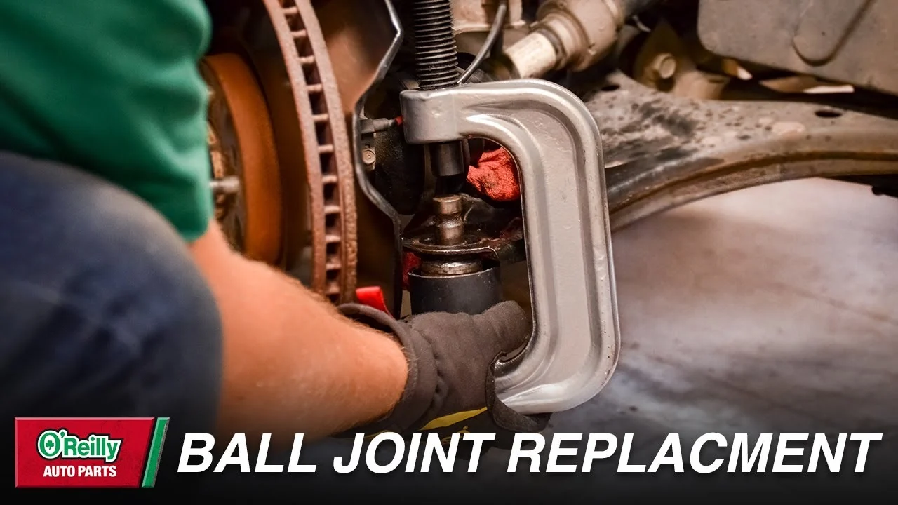
Choose a receiving cup that is large enough for the ball-joint housing to enter without touching the control arm. On the opposite side, place a press adapter that contacts the joint housing or flange evenly and is smaller than the control-arm bore. The adapter must push on the joint, not on the stud, grease fitting, dust boot, or a thin edge.
Arrange the cups so the ball joint moves into the open receiving cup. Check that the press screw or hydraulic ram is centered over the joint. A slight angle can create tremendous side loading, making the press slip or forcing the joint into the arm rather than out of it.
Thread the press screw by hand until the adapters are snug. Before adding force, look from two directions to verify that the cups have not shifted and that the control arm is supported directly beneath the joint. Remove the rubber dust boot if it interferes with the adapter or if the old boot is already being discarded.
This is the central setup when learning how to remove a ball joint from a control arm: the receiving cup supports the arm while providing space for the joint, and the driving adapter transfers force to the joint housing. If either cup is the wrong size, stop and get a better adapter instead of improvising with loose sockets.
Step 5 Apply steady pressure and release the joint
Turn the press screw slowly, or operate the hydraulic press with controlled pressure. Watch the joint, cups, and control arm rather than looking only at the press handle. A small movement, a crack of corrosion, or a change in resistance can be normal, but sudden tilting or adapter movement is a reason to unload the press and reset it.
Once the joint begins to move, continue only far enough for the housing to clear the control arm. Do not force the press after the joint has reached the receiving cup. Keep the joint and any loose pieces contained, then release the pressure slowly.
A joint that will not move with a correctly aligned press may be seized by rust, may still have a retaining feature installed, or may require a larger press capacity. Increasing force without checking the setup can bend the control arm or fracture a cup. A hydraulic press is not automatically safer; it can store and release more force if the supports are wrong.
Check your result
Successful removal leaves the control-arm bore open and the arm sitting flat on its supports. The bore should not have a torn lip, raised metal, deep gouges, or a visible crack caused during pressing.
Step 6 Deal with a riveted joint without damaging the arm
If the control arm used rivets, inspect the joint after the heads are removed. The remaining rivet bodies may press out with the joint, but they may also need to be driven through individually with a punch. Support the flange and aim the punch at the center of each rivet rather than at the control-arm sheet metal.
A useful way to approach how to remove a ball joint from a control arm is to check your progress after each stage.
Do not grind the rivet heads so deeply that the grinder touches the joint flange or arm. If a rivet is hardened and refuses to move, make a relief cut in the rivet body or use an appropriate air chisel bit while keeping the tool aligned. Replace all removed rivets with the hardware supplied for the replacement joint; do not install random bolts unless the manufacturer specifically provides that conversion.
After the old joint is out, remove burrs left by the rivets with a file or abrasive pad. The replacement joint’s flange must sit flush against the arm. A remaining rivet head or raised burr can hold the joint crooked and prevent its fasteners from clamping evenly.
Step 7 Clean and inspect the control-arm bore
Brush rust, dirt, and loose metal from the bore. Wipe the area clean so you can see the complete edge of the opening. Do not enlarge the bore with a drill, rotary tool, or aggressive grinding; the press fit is part of the joint’s retention.
Inspect for an oval opening, cracks radiating from the bore, a folded lip, deep corrosion pits, or metal that has been pushed outward. Also inspect the surrounding control arm and its bushings. A new ball joint cannot correct a bent arm or a damaged mounting area.
If the bore is only lightly dirty, a wire brush and a thin film of the lubricant specified by the joint maker may be appropriate. Some press-fit manufacturers require a dry fit, so follow the replacement instructions rather than applying grease automatically. Do not use lubricant to compensate for a joint that is the wrong size.
Step 8 Stop when the arm is not safe to reuse
Set the control arm aside for replacement or professional evaluation if the bore is loose, the arm is cracked or bent, or the joint was removed only by severe deformation of the mounting area. The same applies if you cannot identify the correct replacement joint or cannot establish the original installation direction.
A damaged control arm is a suspension failure risk, not merely a cosmetic problem. Do not weld, peen, or shim the bore as an improvised repair unless a qualified repair procedure specifically allows it. When in doubt, replacing the complete arm may be safer and more practical than pressing in another joint.
Choosing the right removal method
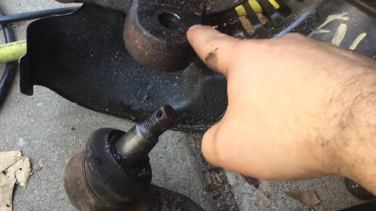
Most press-in ball joints can be removed with a screw-type ball joint press when the control arm is off the vehicle. The kit must include cups that fit the particular joint and arm; a universal kit is useful only when its adapters actually match the dimensions.
Ball joint press versus hydraulic press
A screw press is often easier for a home mechanic because force is applied gradually and the setup can be repositioned on the bench. It still requires a strong frame, undamaged cups, and a breaker bar used without sudden jerking.
A hydraulic press can handle a severely seized joint, but it demands especially careful support. Use flat, rated plates or blocks that cannot roll, and keep the press bed and ram aligned. Never use stacked loose sockets, soft wood, or pieces that can shatter as the primary support under high pressure.
Why hammer-only removal is a poor default
Heavy blows can distort a control arm, damage the joint bore, and send metal fragments outward. A hammer and punch are reasonable for removing rivet remnants or breaking light corrosion after the retaining hardware is gone, but the joint should normally be driven with a properly supported press.
Heat can sometimes expand a surrounding steel arm, but it can damage rubber bushings, coatings, nearby components, and the arm’s heat treatment. Avoid heating an assembly unless the manufacturer’s procedure permits it and you understand exactly which parts must be protected.
Checks before installing the replacement joint
Removal is complete only when the control arm is ready to accept the new part. Before installation, compare the old and new joints one more time and make sure the arm has not been distorted during removal.
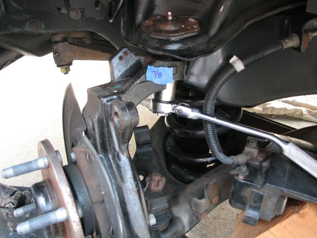
- The replacement housing diameter and flange match the control-arm opening.
- The stud taper, thread size, and stud angle match the original application.
- The snap-ring groove or mounting holes are in the same position.
- The control-arm bore is round, clean, and free of raised burrs.
- The joint’s orientation mark, grease fitting, and dust-boot clearance are understood.
- Any replacement retaining ring, bolts, nuts, or rivets are present and correct.
Do not press the new joint into an arm with a loose or damaged bore. Also avoid striking the new stud or dust boot to make the joint fit. Installation requires its own correct press adapters and the vehicle manufacturer’s seating and torque specifications.
Troubleshooting difficult removal
When the joint will not move, return to the setup rather than immediately adding force. The most common causes are a forgotten snap ring, a cup that is too small, support placed on the wrong section of the arm, or pressure applied to the stud instead of the housing.
| What you observe | Likely cause and response |
|---|---|
| The press leans or the cups walk sideways | Unload it and realign the arm, cups, and ram. Improve the support before trying again. |
| The joint moves, then jams | Rust or a distorted bore may be binding it. Clean the exposed area, confirm the receiving cup is deep enough, and inspect for damage. |
| The control arm flexes noticeably | The supports are too far away or are bearing on a weak section. Stop and support the arm close to the joint on solid surfaces. |
| A riveted joint remains attached after grinding | One or more rivet shoulders may remain. Remove the heads completely and press or punch the bodies out without cutting the arm. |
| The bore edge is raised or cracked | Stop using the arm until it is assessed. Do not hide the damage with a new joint or a shim. |
If a press reaches its limit and the joint has not moved, do not add a long pipe to the handle or strike the loaded press. Use a larger, correctly rated press or take the arm to a shop with the proper fixtures. This is the point to seek qualified help when the part is badly seized or the control arm’s construction is unfamiliar.
Beginner questions about ball joint removal
Can I remove the ball joint while the control arm is still on the vehicle?
Sometimes a vehicle-specific press can do it, but it is not a universal method. The spring, steering knuckle, brake lines, and nearby components may make the setup unsafe or prevent proper support. Remove the arm first unless the service instructions explicitly describe an on-vehicle procedure.
How do I know whether my ball joint is pressed in?
A press-in joint has a cylindrical housing fitted tightly through the control arm, often with a snap ring or flange. A bolt-in joint has visible bolts or studs around its flange, while a riveted joint has factory rivet heads. Clean the area before identifying the design.
Can I reuse the old snap ring?
Only if the manufacturer permits it and the ring is undamaged, properly shaped, and free of serious corrosion. A replacement joint commonly includes a new ring, which is preferable. The ring must seat completely in its groove before the new joint is put into service.
What if the control-arm bore is slightly larger after removal?
Do not assume a new joint will compensate for a loose bore. Measure it against the manufacturer’s specification or have the arm inspected. If the press fit is lost, the control arm generally needs replacement rather than a homemade shim, peening, or adhesive.
Do I need an alignment after this repair?
Usually, yes. Removing or replacing a control arm can change suspension geometry, and even a small change can affect toe, camber, or caster. Reassemble the vehicle using the specified torque procedures, then have the alignment checked before treating the repair as finished.
Finish with a sound control arm, not just a removed joint
Learning how to remove a ball joint from a control arm safely comes down to controlled force and solid support. Identify the retention method, remove the snap ring or rivets completely, align the press with the joint, and inspect the bore after removal. Never let stubborn corrosion justify a crooked press setup or an improvised repair to damaged metal.
Before installing the replacement, confirm the part and orientation, replace the required retaining hardware, and follow the vehicle-specific installation and torque instructions. If the arm is cracked, bent, badly corroded, or outside your ability to support safely, stop and have the part replaced or evaluated. The final check should include proper reassembly, an inspection of nearby suspension components, and a professional wheel alignment when required.