How to Replace Upper Control Arm Chevy Silverado Safely at Home
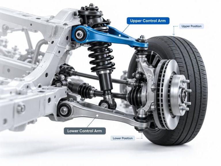
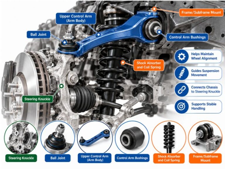
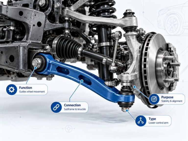
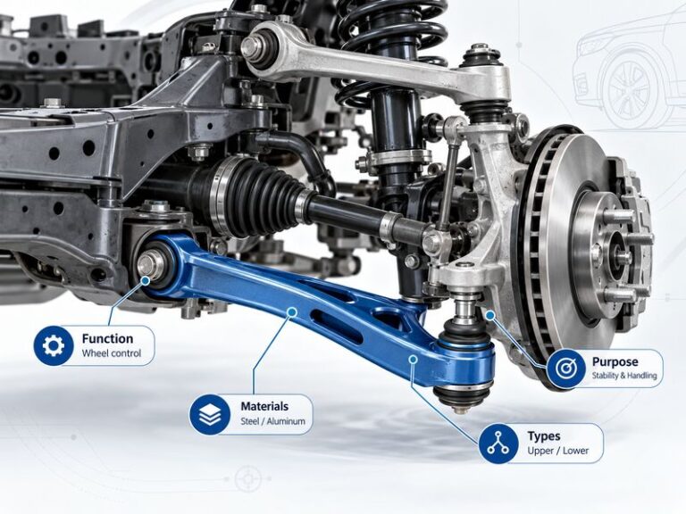
A worn upper control arm can make a Chevy Silverado feel loose, noisy, or unpredictable over bumps. You may hear a clunk from the front suspension, notice uneven tire wear, or feel the truck wander when braking. The upper control arm connects the frame to the steering knuckle, so its bushings and ball joint affect both wheel control and alignment.
Replacing one is a realistic driveway repair for a careful beginner, but it is not a job to rush. The truck must be supported securely, the spring or torsion-bar load must be treated with respect, and the replacement arm must match the exact year, trim, drivetrain, and suspension design. A service manual is especially useful for torque specifications.
This guide explains how to replace upper control arm chevy silverado components from preparation through final inspection. You will learn how to identify the correct part, remove the old arm, install the new one without damaging the bushings, check your work, and know when a professional alignment or additional diagnosis is necessary.
At a glance
- Support the Silverado by the frame and keep a second support under the lower control arm while working.
- Do not rely on an impact wrench for final torque, and tighten pivot-bolt hardware with the suspension at normal ride height when specified.
- A wheel alignment is normally required after control-arm replacement, even when the truck drives normally.
How to Replace Upper Control Arm Chevy Silverado Safely
The general procedure is similar on many Silverado models with independent front suspension, but the details vary. Two-wheel-drive and four-wheel-drive trucks can use different arms, ball joints, fasteners, and alignment arrangements. Confirm the exact application before taking anything apart, and use the factory torque specifications for your model rather than copying values from another year.
Tools you will need
- Correct replacement upper control arm, matched to the Silverado’s year, trim, drivetrain, and side
- Floor jack and sturdy jack stands rated for the truck
- Wheel chocks to prevent movement
- Socket and wrench set, including the sizes required for the control-arm and ball-joint fasteners
- Torque wrench with the range needed for suspension fasteners
- Ball-joint separator or pickle fork, used carefully to separate the tapered stud
- Penetrating oil and a wire brush for corroded threads
- Paint marker or scribe for recording the original alignment position
- Optional: pry bar, hammer, replacement cotter pins, and a service manual for model-specific instructions

Step 1 Confirm the replacement arm and inspect the suspension
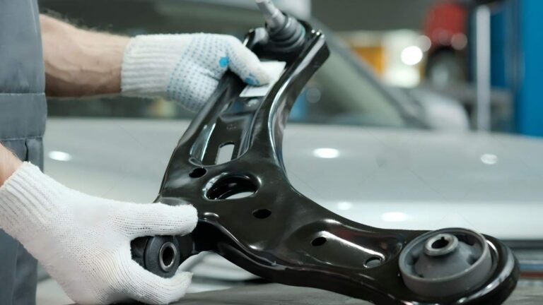
Park on a firm, level surface and compare the new control arm with the installed part before lifting the truck. Check the shape, mounting width, ball-joint position, bushing style, and left- or right-hand designation. Some replacement arms include a new ball joint; others require transferring or pressing one, which is a different task.
Look for the source of the problem before committing to the repair. A cracked bushing, torn ball-joint boot, excessive play, or bent arm supports replacement. Also inspect the lower ball joint, tie-rod end, sway-bar link, shock, brake hose, and wheel bearing.
Replacing the upper arm will not correct looseness caused by another worn component.
Read the replacement part’s instructions. If it requires a specific orientation, spacer, washer, or supplied hardware, keep those pieces together. Do not assume the old bolts and nuts should automatically be reused; many suspension parts use prevailing-torque nuts or one-time-use hardware.
Step 2 Loosen the wheel hardware and lift the Silverado
With the truck still on the ground, loosen the front wheel lug nuts slightly. Do not remove them yet. Set the parking brake, place the transmission in Park, and chock the rear wheels.
If the truck has a manual transmission, leave it in gear as well as using the parking brake.
Place the floor jack under a manufacturer-approved lifting point and raise the front of the truck high enough to remove the wheel. Position jack stands under solid frame support points, then lower the truck gently onto them. Shake the truck lightly at a safe body location to confirm that it is stable before putting your hands near the suspension.
Leave the jack under the lower control arm with light contact, or place a second suitable support beneath it. This does not replace the frame jack stands; it helps control the suspension as fasteners are removed. Never work under a truck supported only by a hydraulic jack.
Important
The front suspension can store substantial spring energy. Do not loosen or remove a torsion-bar anchor, coil-spring retainer, or other spring-related component unless you have the correct procedure and equipment. If the upper arm is under unusual tension or the truck has a modified suspension, stop and use a qualified repair shop.
Step 3 Remove the wheel and document the original setup
Remove the lug nuts and wheel, then slide the wheel under the frame as an extra backup. Keep the brake rotor and caliper supported normally; do not let the brake hose carry the caliper’s weight. If access requires moving the caliper, hang it with suitable wire or a purpose-made hook rather than leaving it suspended by the hose.
Use a paint marker to mark the relationship between the control-arm pivot hardware and its mounting area if the design allows it. On many trucks, the upper-arm pivot position influences camber and caster. The marks are not a substitute for an alignment, but they provide a useful reference during reassembly.
Take clear photos of washers, shims, spacers, and bolt orientation before removal. A Silverado may have alignment shims or eccentric hardware depending on the suspension design. Keep parts from the front and rear pivots separate so they cannot be accidentally swapped.
Step 4 Disconnect the upper ball joint from the steering knuckle
Find the upper ball-joint stud where it passes through the steering knuckle. Remove the cotter pin, if fitted, and loosen the nut while leaving it threaded on a few turns. That remaining nut prevents the knuckle from dropping suddenly when the tapered stud releases.
Use a ball-joint separator between the control arm and knuckle, following the tool maker’s instructions. A pickle fork may damage the ball-joint boot, which is acceptable only if the joint is being discarded, but it can also damage nearby surfaces if used carelessly. Do not strike the threaded stud directly with a hammer; the threads can mushroom and prevent the nut from starting.
Once the taper separates, support the steering knuckle so it does not hang from the brake hose or pull on the axle shaft. Remove the ball-joint nut and move the knuckle just far enough to free the stud. If it will not separate with reasonable force, use a better separator rather than heating or violently hammering the assembly.
Step 5 Remove the upper control-arm pivot hardware
Support the lower control arm and steering assembly so the upper arm is not carrying an uncontrolled load. Identify the nuts, washers, shims, and sleeves at the upper-arm pivots. Remove the hardware carefully and place it in order on a clean surface.
If the pivot bolts are seized inside the bushings, penetrating oil and gentle working may help. Avoid cutting or heating near brake lines, wiring, fuel components, rubber bushings, or a loaded spring. If a bolt will not move without force that could damage the frame, stop and get experienced assistance.
Pull the old arm out only after confirming that all fasteners and the ball-joint connection are free. Compare it with the replacement arm on the floor. The new arm should have the same general orientation, and the ball-joint stud should point in the same direction unless the manufacturer’s instructions say otherwise.
Step 6 Prepare and position the new upper control arm
Clean the mounting surfaces with a wire brush and inspect the frame brackets for cracks, elongated holes, or heavy rust. Check that the replacement bushings are seated evenly and that the ball-joint boot is not twisted or pinched. Do not apply grease to sealed components unless the part specifically has a grease fitting and its instructions call for it.
Place the new arm into the frame brackets with the original spacers, washers, or alignment hardware in their recorded positions. Install the pivot bolts and nuts by hand first. The threads should start easily; forcing a nut with a wrench can cross-thread the fastener and create a dangerous repair.
At this stage, tighten the pivot hardware only enough to hold the arm in place. Rubber control-arm bushings can be preloaded if their bolts are fully tightened while the arm hangs at full droop. Final tightening is generally performed with the suspension at normal ride height, but follow your model’s service instructions because some aftermarket arms use a different bushing design.
Step 7 Reconnect the ball joint and install new locking hardware
Guide the ball-joint stud into the steering knuckle without forcing it sideways. Install the specified nut and tighten it to the vehicle’s service-manual specification. If the nut’s slot does not line up with the cotter-pin hole at the specified torque, continue tightening only as the manufacturer permits; never loosen the nut to align the hole.
Install a new cotter pin where the design uses one. Bend its ends so it cannot work out, and do not reuse a damaged pin. If the replacement assembly uses a prevailing-torque nut or a different locking method, use the supplied hardware rather than substituting an ordinary nut.
A useful way to approach how to replace upper control arm chevy silverado is to check your progress after each stage.
Check that the ball-joint boot is seated and clear of the knuckle. Turn the steering slightly from side to side and watch for contact with the brake hose, ABS wire, wheel, or control arm. The steering should move without binding while the vehicle remains supported.
Step 8 Set the suspension at ride height and torque the pivots
Before final tightening, support the lower control arm with the jack and raise it slowly until the suspension approaches its normal ride-height position. Do not lift the truck off the jack stands. Use the service manual’s ride-height reference or the manufacturer’s specified method; the correct position is not always simply the point where the shock appears vertical.
With the arm positioned correctly, torque the pivot fasteners and ball-joint nut to the specified values. Use a calibrated torque wrench for final tightening, keep the wrench aligned as instructed, and avoid adding a pipe extension unless the torque calculation accounts for it.
Some aftermarket control arms specify a different tightening procedure, such as tightening with the vehicle on the ground. Follow the arm manufacturer’s instructions when they are more specific than a general repair description. The important result is that the bushings are not clamped in a severely twisted position.
Helpful tip
Paint-mark the fastener and nearby metal only after the correct torque is applied. The mark is a quick visual reference for movement later, but it does not replace a torque check or alignment inspection.
Step 9 Reinstall the wheel and lower the truck safely
Reinstall the wheel and thread the lug nuts by hand. Tighten them in a crisscross pattern while the wheel is still slightly off the ground, then lower the truck fully and torque the lug nuts in the pattern and sequence specified for the Silverado.
Remove the support from beneath the lower control arm only after the truck is securely resting on the ground. Take away the jack stands, remove the wheel chocks, and make sure no tools, old hardware, or support blocks remain under the truck.
Repeat the procedure on the other side only if inspection shows that side also needs service or if the repair plan calls for replacing both arms. Do not replace a good part merely because the opposite side is accessible; diagnose each side, while recognizing that control-arm bushings often wear at similar rates.
Step 10 Perform a stationary safety check before driving
With the truck on the ground, compare the repaired side with the other side. The wheel should sit normally in the wheel opening, the control arm should not touch the frame, and the ball-joint boot and bushings should appear intact. Verify that the brake hose and ABS wire are clipped into their original locations.
Turn the steering wheel slowly from lock to lock while watching the repaired area. Listen for binding or sharp clicks and check that nothing contacts the tire. Press the brake pedal before moving; it may feel different if the caliper or wheel was disturbed, and a soft pedal requires immediate inspection rather than a test drive.
Check your result
A successful stationary check shows no loose hardware, no brake-fluid leak, no stretched wire or hose, no tire contact, and smooth steering movement through the available range.
Step 11 Test-drive carefully and arrange an alignment
Begin with a slow drive in a quiet area. Confirm that the steering returns normally, the truck does not pull sharply, and there is no clunk when braking or crossing a small uneven surface. Stop immediately if the steering feels loose, the wheel is badly off-center, or a metallic impact repeats.
After the short check, inspect the wheel and control-arm area again. A newly installed arm can expose a separate worn component, and a loose fastener may become visible before it causes a larger problem. Recheck accessible fasteners according to the part manufacturer’s instructions.
Schedule a four-wheel alignment or the alignment service specified for your truck. The upper control arm affects front camber and caster, and even a small change can cause tire wear or steering pull. A professional alignment also provides a useful final check that the frame, steering, and suspension are within adjustment range.
What the upper control arm does and why alignment matters
The upper control arm is a suspension link that pivots on bushings at the frame and connects to the steering knuckle through an upper ball joint. It helps control the top of the wheel as the suspension moves while allowing the steering knuckle to turn.
The ball joint is a swiveling connection, while the bushings isolate movement and road vibration at the frame. Wear in either part can cause play, noise, unstable tracking, or irregular tire wear. A control arm may also be bent by a curb impact even if its bushings do not look torn.
Camber describes how much the top of the tire leans inward or outward when viewed from the front. Caster describes the steering-axis angle when viewed from the side and influences straight-line stability and steering return. Changing the upper arm or its pivot position can affect both, which is why an alignment is part of the repair rather than an optional cosmetic adjustment.
If you are learning how to replace upper control arm chevy silverado parts because of a clunk, confirm that the noise actually comes from the upper arm. A sway-bar link, lower ball joint, shock mount, or loose brake component can produce a similar sound.

How to verify the repair before and after alignment
Verification has two parts: a physical inspection and a driving check. The physical inspection should find no missing cotter pin, exposed or damaged ball-joint boot, misplaced spacer, loose pivot hardware, or interference with the wheel and brake components.
Use a practical inspection checklist
- Confirm that the upper-arm pivot nuts and ball-joint nut were torqued to the correct specifications.
- Confirm that locking hardware, such as cotter pins or supplied locknuts, is installed correctly.
- Check that the control-arm bushings are not twisted, split, or pinched.
- Verify that brake hoses and ABS wires follow their original routing.
- Check the wheel lug-nut torque after the truck is fully on the ground.
- Look for tire-to-suspension contact with the steering turned both directions.
- Check for a straight steering wheel and normal return after the initial drive.
Understand what an alignment report can reveal
An alignment report may show that camber or caster is outside the adjustment range. That can indicate incorrect spacer placement, a bent suspension component, frame damage, or a replacement arm that does not match the truck. Do not force an alignment technician to compensate for a wrong part or damaged mounting bracket.
After alignment, monitor the front tires for the next several drives. Feathered tread, rapid wear on one edge, or a new pull deserves another inspection. If the steering wheel remains off-center after alignment, ask the shop to verify the adjustment rather than simply moving the wheel on the column.
Common problems during upper control-arm replacement
Most difficulties come from corrosion, incorrect part selection, or suspension load. The following checks help separate a normal challenge from a reason to stop.
| What you notice | Likely concern | Best response |
|---|---|---|
| Ball-joint stud will not separate | The taper is still tightly seated or the separator is unsuitable | Use the correct separator and protect surrounding parts; do not hammer the threaded stud directly |
| Pivot bolt will not slide out | Rust has bonded the bolt to the bushing sleeve, or the frame bracket is damaged | Stop before applying heat or cutting near hoses, wiring, or spring components; seek experienced help |
| New arm does not match the old arm | Wrong year, side, drivetrain, or suspension application | Do not install it; verify the part number and return for the correct arm |
| Clunk remains after replacement | Another joint or bushing is worn, or hardware is loose | Recheck torque and inspect the lower ball joint, tie rod, sway-bar link, and shock mount |
| Truck pulls or tire wears unevenly | Alignment changed or a component is bent | Have the truck aligned and inspect the alignment readings for underlying damage |
If the upper arm is difficult to remove because the truck has a torsion-bar system, remember that the torsion bar is not the same thing as the control arm. Do not disturb its anchor or adjuster simply to gain access. A loaded torsion bar requires a specific unloading procedure and a suitable tool.
Upper control-arm replacement FAQs
Can I replace only one upper control arm?
Yes, if inspection shows that only one arm is worn or damaged. Compare the other side and consider its age and condition, but replace both only when both are defective or your repair plan specifically calls for it.
Do I need a special tool to remove the upper ball joint?
A ball-joint separator makes removal safer and more controlled. A pickle fork can work when the old arm or ball joint will be discarded, but it may damage the boot and can harm nearby components if used carelessly.
Can I drive without an alignment after installing the arm?
Only drive far enough for a cautious inspection or directly to an alignment facility if the truck is safe to operate. The control-arm position can change camber and caster, causing tire wear or a pull even when the steering initially feels acceptable.
Should the control-arm pivot bolts be tightened with the wheels hanging?
Usually, rubber-bushed pivot bolts should receive final torque at the specified ride-height position to avoid preloading the bushings. The exact procedure depends on the Silverado and replacement arm, so use the service information for your application.
What if the replacement arm includes a different ball joint?
Use the supplied ball joint and hardware only if the arm is designed for that combination and the instructions confirm the installation. Do not mix an incompatible ball joint, nut, spacer, or taper with the original parts.
When should I stop and have a shop finish the job?
Stop if the truck cannot be supported securely, a spring or torsion-bar component is under uncontrolled load, a frame bracket is cracked, a fastener will not release without risky heat or cutting, or you cannot confirm the correct torque specifications. Suspension and steering mistakes can cause loss of control.
Finish the repair with an alignment and careful inspection
Learning how to replace upper control arm chevy silverado components is manageable when the truck is supported correctly, the suspension load is respected, and every fastener is installed with the correct hardware and torque. The replacement itself is only part of the job: inspect related steering parts, verify brake and ABS routing, perform a cautious drive, and arrange a professional alignment.
If the truck still clunks, pulls, or shows abnormal tire wear, do not keep driving in the hope that the symptoms will disappear. Recheck the installation and have the front suspension inspected. A careful final inspection is what turns a parts swap into a dependable repair.