How to Replace Control Arm With Ball Joint: Complete DIY Guide
A worn control arm can make a vehicle wander, pull during braking, or clunk over bumps. When the ball joint is built into the control arm, replacing the complete assembly is often more practical than pressing in a separate joint. The job is manageable for a careful beginner, but it involves supporting the vehicle and controlling a spring-loaded suspension system, so preparation matters more than speed.
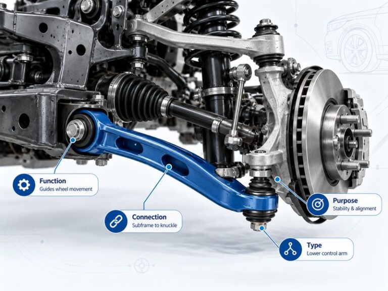
This guide explains how to replace control arm with ball joint on a typical vehicle that uses a bolt-in lower control arm and a ball joint attached to the steering knuckle with a tapered stud. The exact fastener locations, torque values, and removal method vary by vehicle. Your repair manual is the authority for those details, especially if the suspension uses a coil spring mounted directly on the control arm.
You will learn how to confirm the correct replacement part, support the vehicle, separate the old joint without damaging nearby components, install the new arm at the right ride-height position, and check the result. If a spring is captured by the control arm or you cannot safely support the vehicle, stop and use a qualified repair facility instead.
At a glance
- Use vehicle-specific torque specifications and support the steering knuckle before separating the ball joint.
- Tighten rubber-bushed control-arm bolts at normal ride height unless the manufacturer states otherwise.
- Plan on a wheel alignment after changing a control arm, even if the vehicle feels normal.
How to replace control arm with ball joint safely
This procedure applies to a common lower control arm that includes a preinstalled ball joint. It is not a universal sequence: some vehicles use riveted joints, separate upper and lower arms, torsion bars, or a coil spring that bears directly on the arm. Confirm the design before lifting the vehicle.
Tools you will need
- Vehicle service information or a repair manual for torque values and suspension warnings
- Floor jack and appropriately rated jack stands for supporting the vehicle
- Wheel chocks to prevent movement
- Socket and wrench set, including the sizes used for the control-arm fasteners
- Torque wrench for final tightening
- Ball-joint separator or suitable separator tool
- Penetrating oil and a wire brush for corroded threads
- Replacement control arm with the correct integrated ball joint and any required new nuts or bolts
- Paint marker or scribe for recording the original position, when useful
- Optional: pry bar, rust penetrant, and a second jack for supporting the knuckle or arm
Step 1 Confirm the suspension design and replacement part
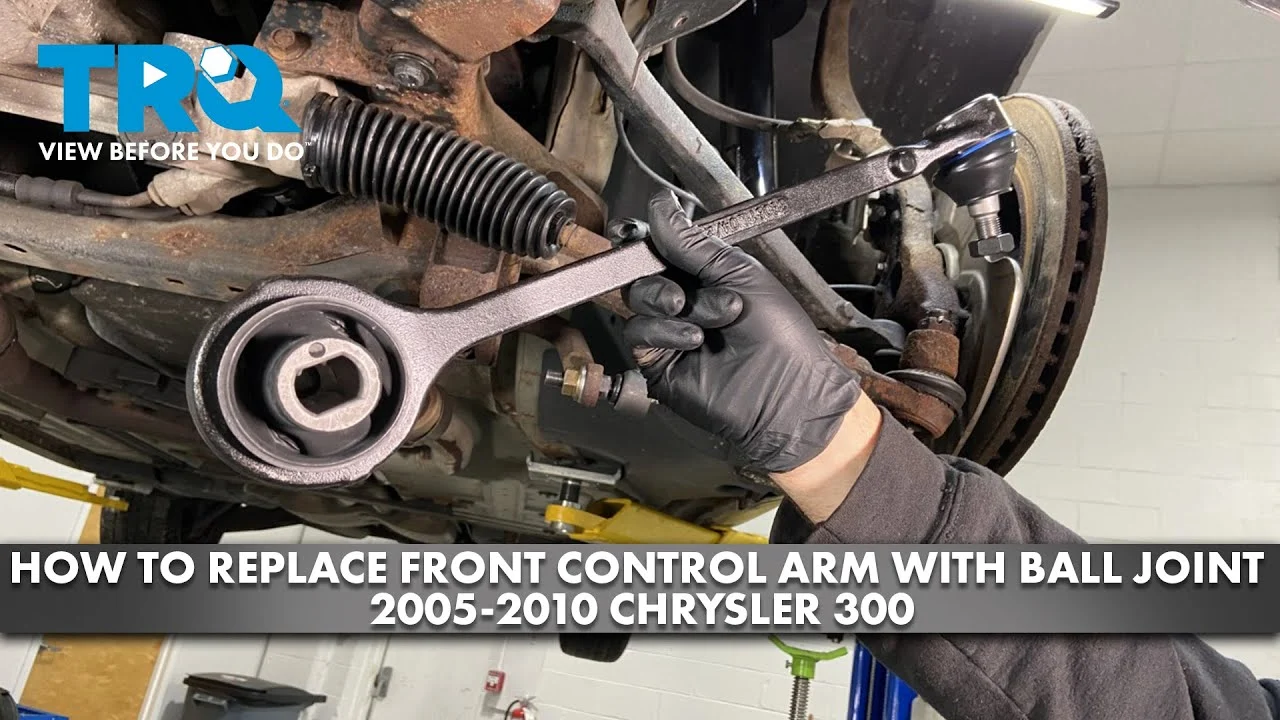
Look up the vehicle by year, make, model, engine, and drivetrain, then compare the new control arm with the old one before removing anything. Check the mounting-hole pattern, bushing shape, ball-joint stud angle, brake-line bracket, sway-bar attachment, and whether the part is for the driver or passenger side.
Read the repair information for spring placement and required one-time-use hardware. A control arm that carries a coil spring, torsion bar, or other stored suspension force may require a special unloading procedure. Do not loosen its pivot bolts or ball-joint hardware until you know how that force is safely controlled.
Inspect the replacement ball-joint boot. It should be seated evenly without cuts, splits, or grease leakage. Compare the new bushings with the old ones; a small difference in orientation can matter because some bushings are designed to twist in one direction.
Step 2 Prepare a level work area and loosen the wheel hardware
Park on a hard, level surface, select Park or first gear, set the parking brake, and chock the wheels that will remain on the ground. If the vehicle has air suspension, follow its manufacturer-specific procedure before lifting it.
Break the wheel lug nuts loose while the tire is still on the ground, but do not remove them yet. Do not rely on a hydraulic jack alone. The jack raises the vehicle; the jack stands carry it while you work.
Important
Never place any part of your body under a vehicle supported only by a jack. Position jack stands at the manufacturer’s approved support points, and make sure the stands contact solid structure rather than thin floor or suspension panels.
Step 3 Raise and support the vehicle securely
Lift the vehicle at the specified jacking point and place jack stands under the approved structural points. Lower the vehicle gently onto the stands, then give the body a careful push near the fender to confirm it is stable. Keep the removed wheel nearby only as a backup barrier, not as a substitute for stands.
Remove the wheel and place it aside. Turn the steering as needed for access, but avoid stretching the brake hose or pulling on the wiring for the wheel-speed sensor. If the steering knuckle is now unsupported, place a second jack beneath a strong, non-damaging point on the knuckle or hub assembly.
Step 4 Inspect and document the original assembly
Before disconnecting anything, photograph the control arm from several angles. Mark the position of eccentric washers, alignment cams, or slotted bolt heads with a paint marker. These marks may help the vehicle move safely to an alignment shop, but they do not replace an alignment or guarantee the original setting was correct.
Identify every connection attached to the arm. Depending on the vehicle, these may include the ball joint, inner pivot bolts, sway-bar end link, brake-hose bracket, or a ride-height sensor link. Do not force a brake hose, ABS wire, or sensor bracket out of the way.
Step 5 Apply penetrant and remove attached brackets or links
Brush loose rust from exposed threads and apply penetrating oil where appropriate. Give it time to work while you locate the correct wrench sizes. Avoid spraying penetrant onto brake friction surfaces, rubber boots, or the brake rotor.
Remove any brake-line or wheel-speed-sensor brackets secured to the control arm. If the sway-bar end link attaches to the arm, remove its nut while holding the stud or opposing fastener as the design requires. Keep track of washers and spacers in their original order.
If a nut spins with a ball-stud, use the correct counterhold rather than gripping the threaded portion with locking pliers. Damaging the stud can make reassembly difficult and can compromise the replacement hardware.
Step 6 Support the steering knuckle before separating the ball joint
Place a jack or sturdy support under the steering knuckle or hub assembly, using a block or adapter that will not damage the component. The support should carry the knuckle’s weight without lifting the vehicle off the stands. This prevents the knuckle from pulling on the brake hose or driveshaft when the ball joint releases.
Remove the ball-joint nut only after the knuckle is supported. Many ball joints use a castellated nut and cotter pin; replace the cotter pin rather than reusing it. If the joint has a pinch bolt instead of a nut, follow the vehicle’s specified removal direction and do not substitute a different bolt.
Step 7 Separate the old ball joint from the steering knuckle
Use a ball-joint separator that fits the joint and allows the stud to release from its tapered seat. Protect the rubber boot and nearby brake components. A sharp release or pop is normal when a tapered stud breaks free, so keep your hands clear of the tool and joint.
On some assemblies, striking the side of the knuckle’s ball-joint boss with a hammer can help loosen the taper, but strike only the solid boss and never the threaded stud. Do not hammer directly on an aluminum knuckle, sensor, brake rotor, or the ball-joint boot. If corrosion has bonded the parts together or the knuckle begins to deform, stop rather than escalating force.
Once the taper separates, confirm that the knuckle remains supported. Move the arm only as much as necessary; excessive movement can stress the axle, brake hose, or stabilizer link.
Step 8 Remove the control-arm pivot fasteners
Support the control arm with a jack before removing its inner pivot nuts and bolts. The arm may be under spring or bushing tension even when the ball joint is disconnected. Remove the fasteners in a controlled manner while watching for movement.
Some pivot bolts cannot slide out until the subframe, exhaust, or another component is moved. Do not cut or heat a bolt near a fuel line, brake line, wiring, or rubber bushing without a vehicle-specific plan. If a bolt is seized inside the bushing sleeve, the arm may need to be cut out and the sleeve carefully removed; this is a reasonable point to seek professional help.
Compare the removed arm with the replacement before discarding it. Confirm the new part has the same pivot orientation and all required brackets. Transfer only components the manufacturer says to reuse, and replace damaged or specified one-time-use hardware.
Step 9 Position the new control arm and install fasteners loosely
Guide the replacement arm into the original position without forcing the bushings into a twisted angle. Install the inner pivot bolts and nuts by hand, leaving them loose enough for the arm to settle. If the arm has an eccentric washer or alignment cam, return it to the marked orientation for initial positioning.
Raise or lower the arm with a jack until the ball-joint stud lines up with the steering knuckle. Never draw a badly misaligned stud into place by tightening the nut; that can damage the taper or create a false feeling of tightness. A useful way to approach how to replace control arm with ball joint is to check your progress after each stage.
Reconnect the ball-joint stud, install the specified nut, and fit a new cotter pin if the design uses one. The pin must pass through the hole after the nut reaches its specified torque. Do not loosen a castellated nut to line up the cotter-pin hole unless the service instructions explicitly allow that practice.
Step 10 Reconnect links, brackets, and the brake or sensor hardware
Reattach the sway-bar link, brake-line bracket, wheel-speed-sensor wire, and any ride-height or routing brackets removed earlier. Make sure each hose and wire follows its original path and cannot rub the tire, spring, axle, or control arm through the steering and suspension range.
Install nuts and bolts in the correct direction and tighten them enough to hold the assembly while you check alignment. Do not fully torque rubber-bushed pivot bolts with the suspension hanging unless the manual specifically says to do so. Tightening at full droop can preload the bushing and shorten its life.
Step 11 Set the suspension near normal ride height and torque the fasteners
Use the jack under the control arm or knuckle to raise the suspension until it is close to normal ride height. A reliable reference is the distance between the hub center and the fender, measured before disassembly if possible. Keep the vehicle supported by the stands while using the jack to position the suspension; do not lift the body off the stands.
Torque the inner pivot fasteners, ball-joint nut, sway-bar hardware, and wheel lugs to the vehicle’s specified values and in the specified sequence. Use a calibrated torque wrench for the final tightening. Torque values are not interchangeable between vehicles, and “tight enough” is not a safe substitute for the specification.
If the vehicle uses a torque-to-yield bolt, prevailing-torque nut, or other single-use fastener, install a new one. Check that the ball-joint stud protrudes as expected and that the tapered connection is fully seated.
Helpful tip
For a rubber-bushed control arm, the key installation detail is usually final pivot torque at normal ride height. This lets the bushing rest near its working position instead of being permanently twisted from full suspension droop.
Step 12 Reinstall the wheel and lower the vehicle
Clean the wheel’s mounting face and the hub face if rust or debris is present. Install the wheel and hand-tighten the lug nuts in a crisscross pattern. Lower the vehicle until the tire touches the ground enough to prevent rotation, then torque the lugs to the specified value.
Before removing the jack stands, look through the wheel opening. Confirm that the brake hose and ABS wire are not stretched, the ball-joint boot is not pinched, and no tool or support remains under the vehicle. Lower it completely and remove the chocks only when the vehicle is ready to move.
Step 13 Perform a stationary safety check
With the vehicle on the ground, turn the steering wheel from side to side while watching the repaired corner. Listen for binding, and verify that the tire does not contact the control arm, sway bar, brake hose, or liner. Press down on the fender several times and listen for a sharp clunk or metal-to-metal contact.
Recheck the visible hardware, but do not retighten a fastener beyond its specified torque. If the wheel sits at an obviously different angle, the steering wheel is badly off-center, or the vehicle leans, do not drive it to an alignment shop; have the installation inspected or arrange towing.
Step 14 Complete a cautious road check and schedule alignment
Drive first at low speed in a quiet area. Test gentle braking, straight-line tracking, and slow turns while listening for looseness. Stop immediately if the vehicle pulls sharply, the steering feels vague, a warning light appears, or you hear repeated popping or clunking.
A control arm can alter camber, caster, and toe, even when its mounting marks are restored. Schedule a four-wheel alignment or the alignment service specified for the vehicle. Ask for a printout showing the before-and-after readings, and keep it with the repair record.
What makes this repair different from a separate ball-joint replacement?
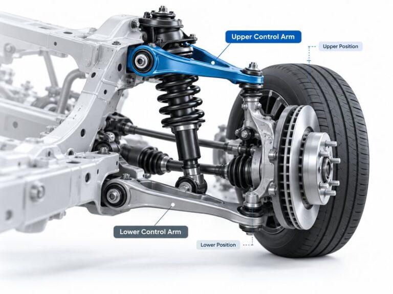
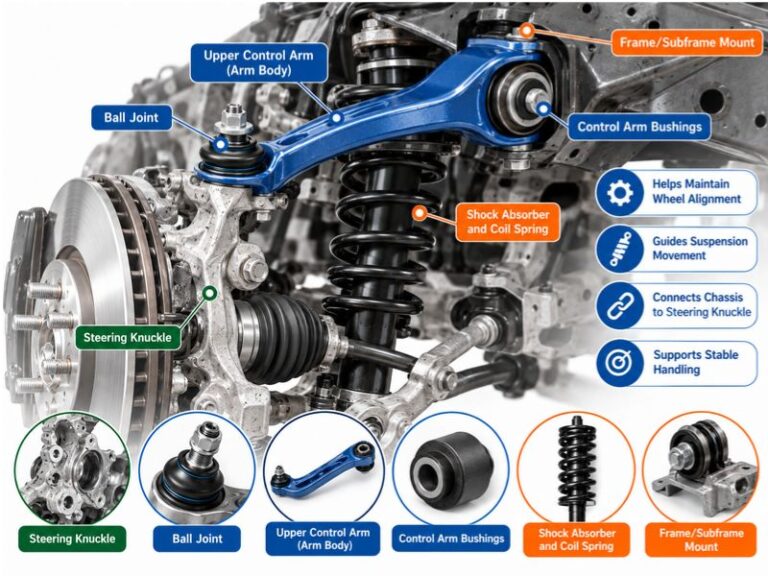
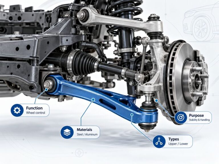
A ball joint is a pivot between the control arm and steering knuckle. It allows the knuckle to move up and down with the suspension while also turning left and right with the steering. The control arm’s inner bushings attach it to the vehicle and control its movement under braking and cornering.
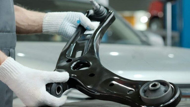
Some vehicles have a ball joint that is pressed or bolted into an existing control arm. Others use a control arm with the ball joint permanently installed or riveted. When the replacement comes as a complete assembly, changing the whole arm avoids pressing equipment and also renews the arm’s bushings.
That convenience does not eliminate compatibility concerns. The ball-joint stud must match the knuckle taper, and the bushings must position the arm correctly. A part that physically bolts in may still be wrong if it changes ride height, sensor routing, alignment range, or the location of the sway-bar connection.

When the job should not be treated as a routine driveway repair
Stop and get qualified help if the vehicle uses a coil spring mounted directly on the control arm and you do not have the correct spring-compression or unloading procedure. A compressed spring stores enough energy to cause severe injury if the arm is released incorrectly.
Professional help is also appropriate when a pivot bolt is seized inside its bushing, the subframe is badly rusted, the steering knuckle is cracked or distorted, or you cannot identify the correct support points. Do not improvise with stacked lumber, a bottle jack placed on a thin component, or a separator that can slip.
How to verify the installation before regular driving
The repair is successful when the new arm is fully seated, all connected components are routed correctly, the hardware is torqued to specification, and the vehicle passes a controlled road check. A quiet test drive alone is not proof that the joint or pivot bolts are correctly installed.

- Confirm the ball-joint nut or pinch bolt is installed and secured according to the manual.
- Confirm new cotter pins or specified replacement fasteners are installed.
- Check that the control-arm bushings are not visibly torn, crushed, or twisted.
- Verify the brake hose and ABS wire have full steering clearance.
- Check wheel-lug torque after the wheel is fully on the ground.
- Look for a loose steering wheel, pulling, uneven braking, or new suspension noise.
- Arrange an alignment before extended or high-speed driving.
If the vehicle has electronic stability control, a steering-angle sensor, or an active suspension system, an alignment may need to be followed by a steering-angle or ride-height relearn. The required procedure depends on the vehicle and should come from its service information.
Common problems after control-arm replacement
Most post-repair symptoms have a small number of likely causes. Use the symptom as a reason to inspect the installation, not as permission to keep driving until the noise disappears.
| Symptom | Likely areas to inspect |
|---|---|
| Clunk over bumps | Loose ball-joint nut, sway-bar link, pivot hardware, or an unsupported brake-line bracket |
| Pulling or an off-center steering wheel | Alignment change, incorrect arm, shifted eccentric, or a tire issue |
| Binding during steering | Ball-joint taper not seated, hose or sensor wire routed incorrectly, or damaged knuckle |
| Uneven tire wear after the repair | Incorrect toe or camber; obtain an alignment and inspect for remaining play |
A new squeak can come from a bushing tightened at full droop. It can also come from a dry or damaged ball-joint boot, a brake shield touching the rotor, or a sway-bar link that was disturbed. Do not inject grease into a sealed joint unless the manufacturer specifically provides a grease fitting and procedure.
If the vehicle still has looseness when the wheel is rocked, check for play in the opposite control arm, tie-rod end, wheel bearing, or steering rack. Replacing one control arm does not automatically correct wear elsewhere in the front suspension.
The method for how to replace control arm with ball joint ends with more than a tightened nut: the steering and suspension geometry must be checked. If the alignment readings cannot be brought into specification, the part may be incorrect or another component may be bent.
Beginner questions about the repair
Can I replace only the ball joint instead of the whole control arm?
Sometimes. If the ball joint is separately serviceable, the manufacturer may permit replacement with a press or a bolt-in joint. If the new arm is sold with the joint installed, replacing the complete assembly is usually the intended method, especially when the original bushings are also worn.
Do I need an alignment after replacing a control arm?
Yes, plan on one. Moving the control arm can change caster, camber, or toe, and the original paint marks are only a temporary reference. An alignment is particularly important if the old arm was bent or the vehicle had uneven tire wear.
Should I replace the control arms on both sides at the same time?
Not automatically. Replace the other side if it has cracked bushings, a loose joint, collision damage, or similar wear. If the vehicle uses symmetrical arms and both have comparable mileage, replacing both may provide more consistent suspension behavior, but the inspection should determine the need.
Why can’t I tighten the control-arm bolts while the suspension hangs?
Many control-arm bushings are bonded rubber parts rather than freely rotating sleeves. Tightening them at full droop can lock in a twist, causing premature bushing failure and changing suspension behavior. Use the vehicle’s specified ride-height position for final torque.
Is a ball-joint separator required?
It is the safest and most controlled choice for a beginner, though some designs can be separated with the manufacturer’s approved technique. Avoid pickle forks when you intend to reuse the joint, because they can tear the boot. Never strike the threaded stud or use uncontrolled force near the knuckle.
Finish the repair with alignment and a careful check
Learning how to replace control arm with ball joint is realistic when the assembly is compatible, the vehicle is supported correctly, and the suspension design does not require hazardous spring removal. Work methodically: document the original layout, support the knuckle and arm, use the correct separator, torque fasteners at the proper suspension position, and protect every brake and sensor line.
After the installation, complete the stationary inspection and a slow road check, then have the alignment measured. If any fastener will not seat, any component is corroded beyond safe removal, or the vehicle behaves unpredictably, stop driving and arrange a professional inspection rather than guessing at the cause.