How to Change Control Arm Ball Joint: Step-by-Step Instructions
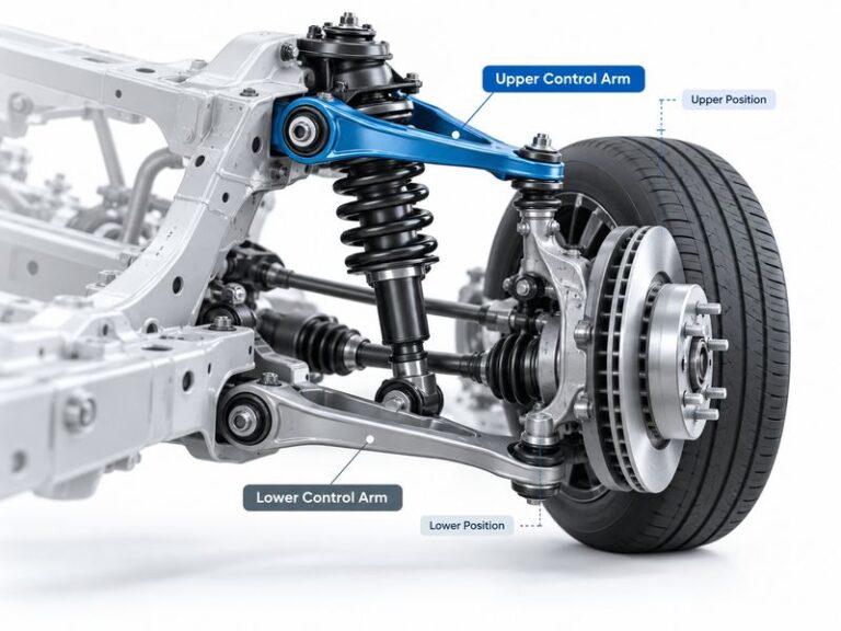
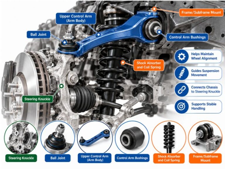
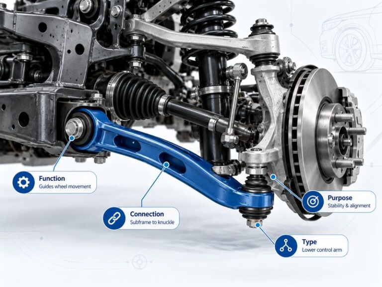
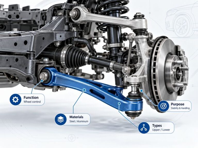
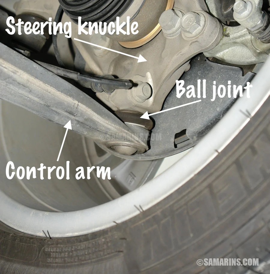
A worn control arm ball joint can make a vehicle feel loose, noisy, or unpredictable. You may hear a clunk over bumps, notice uneven tire wear, or feel the steering pull and wander. Because the ball joint connects the control arm to the steering knuckle, its condition affects how the wheel is located and how the suspension moves.
Replacing one is a realistic project for a careful home mechanic, but it is not a simple bolt-on repair for every vehicle. Some joints are secured with bolts, while others are pressed into the control arm or held by factory rivets. A damaged joint can also leave the wheel unsupported, and a suspension spring may store dangerous energy nearby.
This guide explains how to change control arm ball joint safely, from identifying the correct part and supporting the vehicle to removing a pressed or riveted joint, installing its replacement, tightening the hardware, and checking the result. If your vehicle requires a special press, spring removal, or a procedure you cannot verify in its service information, replacing the complete control arm or using a qualified repair shop may be the safer choice.
At a glance
- Confirm whether your ball joint bolts in, presses in, or uses factory rivets before buying tools.
- Support the vehicle by its structure, never by a jack alone, and keep hands clear while separating the joint.
- Use the vehicle-specific torque specifications and arrange a wheel alignment if suspension geometry was disturbed.
How to change control arm ball joint safely and correctly
The general method is similar for a lower or upper ball joint, but the exact access, fasteners, and removal direction vary by vehicle. Read the repair information for your year, make, model, and suspension configuration before starting; a diagram or service procedure can prevent installing the joint upside down or damaging a tapered stud.
Tools you will need
- Vehicle-specific replacement ball joint, new retaining hardware, and a new cotter pin if specified
- Floor jack and properly rated jack stands for lifting and supporting the vehicle
- Wheel chocks and basic hand tools, including sockets, wrenches, and a breaker bar
- Torque wrench capable of reaching the required suspension fastener specifications
- Ball-joint separator or pickle fork for releasing the tapered stud
- Ball-joint press or suitable hydraulic press for a pressed-in joint
- Wire brush, penetrating oil, and rust penetrant for cleaning and loosening corroded hardware
- Eye protection, mechanic’s gloves, and a hammer; an angle grinder or drill may be needed for rivets
- Optional: service manual, digital camera, and paint marker for recording orientation
Step 1 Confirm the failed joint and identify the replacement
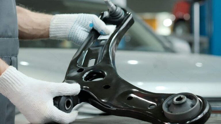
Park on a hard, level surface, set the parking brake, and chock the wheels that will remain on the ground. Before lifting anything, compare the new ball joint with the old assembly or the vehicle’s parts information. Check the stud shape, mounting flange, grease fitting, dust boot, bolt pattern, and whether the part is intended for the upper or lower control arm.
A ball joint can be diagnosed incorrectly when the real problem is a wheel bearing, tie-rod end, sway-bar link, control arm bushing, or loose wheel. With the vehicle safely lifted later, you can check for movement, but do not use a loose or damaged joint as a reason to drive the vehicle to a shop. If the wheel visibly shifts, the stud is separating from the housing, or the dust boot has allowed severe corrosion, treat the vehicle as unsafe to drive.
Look closely at how the original joint is retained. A bolt-in joint has bolts or nuts around its flange. A riveted joint has several large factory rivets that must be drilled or ground away.
A pressed joint has a cylindrical body fitted tightly into the control arm and normally requires a ball-joint press. The replacement method depends on this construction.
Step 2 Loosen the wheel hardware and lift the vehicle securely
Break the wheel lug nuts loose slightly while the tire is still on the ground, but do not remove them yet. Consult the owner’s manual or service information for the approved lifting points. Raise the vehicle with the floor jack and place jack stands under solid structural support points, such as the specified frame or reinforced subframe locations.
Lower the vehicle gently onto the stands and give the body a careful push near the supported area. It should remain stable without rocking or settling. Keep the jack under an appropriate control-arm or subframe location only as a secondary support when the procedure allows; never work beneath a vehicle supported only by a hydraulic jack.
Important
Do not place a jack stand under a thin floor panel, suspension link, or other point that can bend or slip. If the vehicle uses a coil spring mounted in or near the control arm, stop and obtain the correct spring-compression procedure before loosening components that could release spring force.
Step 3 Remove the wheel and document the suspension layout
Remove the lug nuts and wheel, then slide the wheel under the vehicle as an additional precaution if space permits. Photograph the ball joint, brake hose routing, wire clips, washers, and fastener orientation before disassembly. Marking the position of eccentric washers or alignment cams can help you return them to approximately their original positions, although it does not replace a professional alignment.
Inspect the exposed area. Identify the ball-joint nut and cotter pin, the control-arm mounting bolts, the steering knuckle, and any brake or wheel-speed-sensor wiring attached to the control arm. Support the knuckle or hub with a separate jack stand or suitable support so its weight does not pull on the brake hose or sensor cable when the joint is released.
Step 4 Release the tapered ball-joint stud from the steering knuckle
Remove the cotter pin, if fitted, and loosen or remove the ball-joint nut according to the service procedure. Some designs use a castellated nut, while others use a prevailing-torque nut or a pinch bolt. A cotter pin is a one-time-use locking device; plan to replace it rather than reinstalling a bent or broken one.
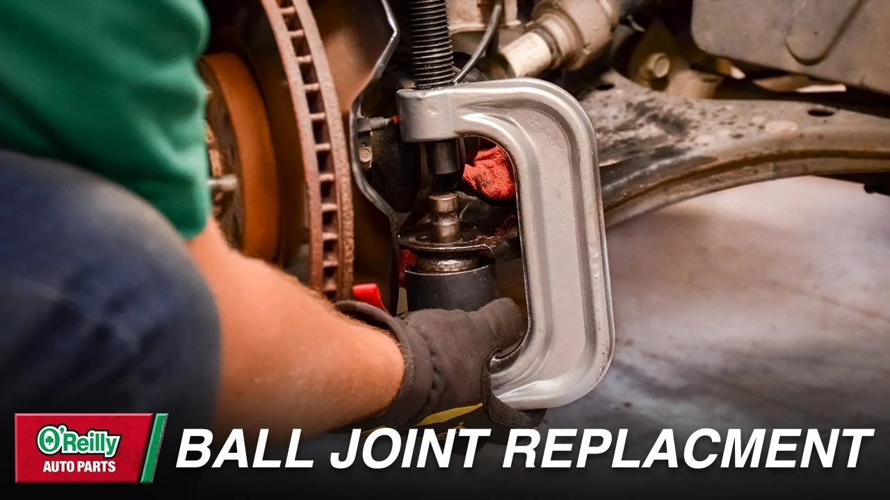
Thread the nut back on a few turns if the procedure permits. This gives the stud somewhere to land and protects the threads while you use a separator. A dedicated ball-joint separator is usually less destructive than a pickle fork, especially if the joint might be reused, although a worn joint being replaced can be separated with a fork when access allows.
Apply steady pressure with the separator, then strike the side of the steering-knuckle boss with a hammer if the service procedure permits. Do not hammer directly on the threaded stud, and do not strike an aluminum knuckle aggressively. When the taper releases, the joint usually makes a sharp pop; keep your fingers away from the gap and support the knuckle.
On some vehicles the ball joint is retained by a pinch bolt rather than a separate nut. Remove the pinch bolt completely and spread the clamp only as specified. Excessive prying can crack the knuckle or distort the bore.
Step 5 Remove the control arm or expose the joint in place
Determine whether the ball joint can be replaced with the control arm installed. A bolt-in joint may be accessible on the vehicle, but a riveted or pressed joint often requires removing the arm for stable, straight pressing. Disconnect only the components needed for access, and keep track of the order of washers and spacers.
If removing the control arm, support it with the jack before taking out its mounting bolts. Remove the ball-joint connection from the knuckle first, then remove the inner control-arm fasteners while watching for spring movement. Many control-arm bushings are tightened with the suspension at normal ride height, so note the original orientation and do not fully torque those bolts while the arm hangs at full droop unless the manufacturer specifically says to do so.
Never allow a coil spring to unload unexpectedly. If the spring is captured by the control arm or the arm must be detached to contain it, use the specified spring compressor and method. A spring compressor that is poorly fitted, damaged, or used at an angle is a reason to stop and have the work performed by a qualified technician.
A useful way to approach how to change control arm ball joint is to check your progress after each stage.
Step 6 Remove the old bolt-in, riveted, or pressed joint
For a bolt-in joint, remove the flange bolts or nuts and lift the joint away from the control arm. Clean the mounting surface and compare the new part’s orientation with the old one. Some joints have an alignment tab or a flange that only fits in one direction.
For a riveted joint, protect nearby parts from metal chips, then grind the rivet heads flush or drill through the rivet centers. Remove the remaining rivet bodies with a punch. Work slowly and wear eye protection; do not enlarge the control-arm holes or grind into the arm.
Replacement joints commonly use bolts and locknuts, but use only the hardware supplied or specified for that application.
For a pressed-in joint, place the control arm in a ball-joint press with the correct receiver cup and forcing adapters. The receiving cup must support the control arm around the joint while leaving room for the joint to move into the cup. Press in the direction shown by the manufacturer, because some joints have a shoulder, snap ring, or retaining lip that determines the removal direction.
Apply penetrant to the joint bore and press gradually. Keep the adapters square with the control arm. If the press starts to tilt, the control arm begins to bend, or the joint will not move despite extreme force, stop rather than adding a longer lever.
The wrong cup arrangement can damage the arm or release suddenly.
Step 7 Clean the bore and install the replacement joint
After removal, scrape rust, dirt, and old coating from the control-arm bore and mounting face. Do not remove sound metal or make the bore larger. Check for cracks, elongated holes, severe corrosion, or a distorted control arm; a new joint cannot safely compensate for a damaged arm.
If the replacement includes a snap ring, install it in its groove before or after pressing as directed. Lightly lubricate the outside of a pressed joint only if the manufacturer allows it. Do not grease a friction-fit surface merely to make installation easier unless the instructions call for it, because lubrication can affect retention.
Press the new joint in squarely and in the correct direction. Push on the joint’s outer housing or the area specified by the manufacturer, never on the threaded stud or ball, and do not transmit press force through the dust boot. The joint is fully seated when its shoulder contacts the arm or the retaining groove is positioned correctly; compare both sides before removing the press.
For a bolt-in or replacement riveted design, position the joint in its original orientation and install all fasteners finger-tight first. Tighten them in a crisscross pattern if the instructions specify one. Keep the dust boot away from tools and do not twist it while turning the stud.
Step 8 Reconnect the joint and reassemble the suspension
Guide the ball-joint stud into the steering knuckle without forcing it at an angle. Install the specified nut or pinch bolt and tighten it to the vehicle-specific torque. If the stud spins while tightening, apply only the approved method to hold it; damaging the stud’s boot or threads can compromise the repair.
Install a new cotter pin through the castellated nut and stud hole when that design uses one. Tighten the nut farther, if necessary, to align the slots with the hole; never loosen it to make the cotter pin fit. Bend the pin ends securely away from moving parts.
Reconnect brake-hose brackets, wheel-speed-sensor wiring, sway-bar links, and any other parts removed for access. Ensure the hose and wiring follow their original route and cannot rub the tire, spring, rotor, or control arm through the full steering range.
Reinstall the control-arm inner bolts and other hardware in their original positions. Snug them for now if the arm’s bushings must be tightened at ride height. Do not substitute ordinary nuts or ungraded bolts for suspension fasteners.
Step 9 Torque the fasteners at the correct suspension position
Use the service information for every critical torque value. The ball-joint nut, pinch bolt, control-arm bolts, wheel lug nuts, and any replacement-joint fasteners may all have different specifications. Torque values are not safely interchangeable between similar-looking vehicles.
If the control-arm bushing bolts are designed to be tightened at normal ride height, support the control arm with a jack and raise it until the hub reaches approximately its normal unloaded driving position, or use the manufacturer’s specified procedure. Keep the vehicle stable on jack stands while doing this. Another option is to torque the inner bolts after the vehicle is lowered, using safe access from the side rather than reaching beneath an unsupported vehicle.
Where the manufacturer specifies torque-to-yield bolts or one-time-use nuts, replace them. Paint marks can show that a fastener moved during reassembly, but they are not a substitute for a torque wrench. Understanding how to change control arm ball joint also means recognizing the limits of the method.
Step 10 Reinstall the wheel and lower the vehicle
Clean the wheel’s mounting face and hub face, place the wheel on the hub, and start every lug nut by hand. Snug the nuts in a star pattern, then lower the vehicle until the tire contacts the ground without carrying the entire vehicle’s weight and torque the lug nuts to the specified value.
Remove the jack stands and lower the vehicle fully. Torque the lug nuts again if the manufacturer’s procedure calls for final tightening on the ground. Confirm that no tool, support, loose wire, or old hardware remains near the brake or suspension.
Step 11 Perform a stationary safety check before driving
Turn the steering wheel slowly from lock to lock while watching the repaired area. The tire, brake hose, sensor wire, dust boot, and control arm should clear one another throughout the movement. Do not continue if the boot folds sharply, the joint binds, the wheel sits at an unusual angle, or any fastener appears loose.
Press the brake pedal until it feels firm if the caliper or brake components were disturbed. Start the engine and listen while turning the wheel at low speed in the driveway, but do not treat a quiet result as proof that the alignment is correct. Check again for a missing cotter pin, unsecured wiring, or a leaking or damaged dust boot.
Which replacement method fits your control arm?
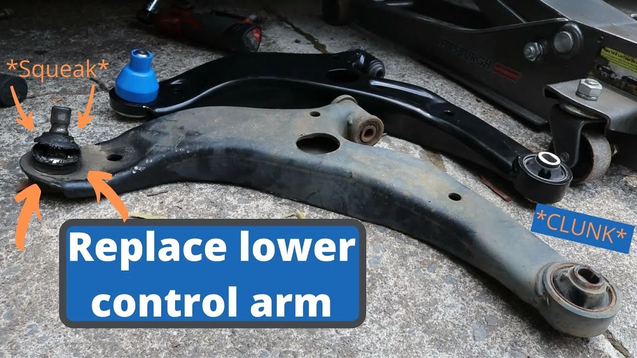
The safest method depends on how the joint is mounted and whether the control arm or spring must be disturbed. A replacement control arm can be more practical than pressing in a joint, but it may cost more and still requires correct bushing orientation and torque. The following comparison helps you choose without forcing one method onto every vehicle.
| Mounting style | What it requires |
|---|---|
| Bolt-in | Basic hand tools, careful flange alignment, and new retaining hardware when specified. |
| Riveted | Drill or grinder, punch, eye protection, and the correct replacement bolts or hardware. |
| Pressed-in | A properly sized ball-joint press or hydraulic press, receiver cups, and careful alignment. |
| Complete control arm | Control-arm removal and installation, bushing-position checks, and ride-height torqueing where required. |
If you do not have a press, ask a parts or machine shop whether they can press the joint out and in with the arm removed. This can be safer than using improvised sockets, threaded rod, or a large hammer. A complete control arm is also worth considering when its bushings are cracked, the arm is corroded, or the joint is difficult to access.
Vehicle-specific instructions matter especially when the ball joint is integrated into the steering knuckle or when the manufacturer does not approve separate replacement. In those cases, the correct repair may be a knuckle or complete control-arm assembly rather than an aftermarket joint.
How to verify the repair before normal driving
A successful installation has more evidence than a new-looking part. The joint should be fully seated, the retaining hardware should be secure, and the wheel should move through steering and suspension travel without contact. Check these points before taking the vehicle onto a public road.
- The ball-joint stud and nut or pinch bolt are installed exactly as specified.
- A new cotter pin is fitted where required, with no attempt to reuse a damaged one.
- Pressed joints are fully seated and their snap rings are installed in the correct groove.
- Brake hoses and wheel-speed-sensor wires are clipped into their original locations.
- Wheel lug nuts and suspension fasteners have been torqued to vehicle-specific values.
- The steering wheel turns freely from lock to lock with no rubbing, binding, or clunk.
- The brake pedal is firm and the vehicle does not pull sharply during a controlled test.
After a short, low-speed test, park on a level surface and inspect the joint area again. Listen for a new clunk and look for a dust boot that is torn, twisted, or leaking grease. If the vehicle feels unstable, stop driving and recheck the work rather than tightening random fasteners.
A wheel alignment is commonly needed after control-arm or ball-joint work, especially if an alignment cam, eccentric washer, steering knuckle, or control-arm mounting position was disturbed. Even when the original marks were restored, worn parts and new joint dimensions can change camber or toe. Uneven steering, a crooked steering wheel, or rapid tire wear are reasons to arrange an alignment promptly.
Common problems and when to stop
Many difficulties come from corrosion, incorrect support, or using the wrong press adapter. The table below points to a sensible response without encouraging excessive force.
| Symptom | Likely issue and response |
|---|---|
| The tapered stud will not separate | Use a proper separator and support the knuckle. Do not hammer the threaded end or pry against a fragile casting. |
| The pressed joint will not move | Recheck press direction and cup alignment. Stop if the arm bends or the press tilts; obtain professional pressing service. |
| The new joint sits crooked | Remove it and inspect the bore and adapters. Do not pull a misaligned joint into place with the retaining bolts. |
| A clunk remains after replacement | Check the other ball joint, tie-rod end, sway-bar link, wheel bearing, control-arm bushing, and wheel fasteners. |
| The vehicle pulls or the wheel is crooked | Check tire pressure and assembly, then have the alignment measured. Do not correct the steering wheel by moving random parts. |
Know when a home repair is not appropriate
Stop and seek qualified help if the vehicle cannot be supported solidly, a coil spring is not safely contained, the control arm or knuckle is cracked, or corrosion has weakened the mounting area. Also stop if you cannot obtain the correct torque specifications or cannot tell whether the replacement joint is fully seated.
A professional inspection is particularly important when the joint has separated while driving, the wheel has folded under the vehicle, or the vehicle has suffered an impact. Those events can bend the control arm, knuckle, subframe, or wheel in addition to damaging the ball joint.
Ball-joint replacement FAQs
Can I change a ball joint without removing the control arm?
Sometimes. Bolt-in joints are often serviceable on the vehicle, but access may be limited. Pressed or riveted joints are usually easier and safer to replace with the control arm removed, especially when a stable press setup is required.
Do I need to replace the control arm with the ball joint?
No, not always. Replace only the joint when the arm is sound and the joint is designed to be serviced separately. Replace the complete arm when the arm is damaged, its bushings are badly worn, or the manufacturer specifies an integrated assembly.
Can I use a pickle fork if I am replacing the joint?
Yes, a pickle fork can separate a joint that will not be reused, but it can damage the dust boot and sometimes the surrounding parts. A dedicated separator is usually preferable when there is enough access.
Why is a wheel alignment needed after ball-joint replacement?
The ball joint helps locate the steering knuckle, and removing the control arm or changing its position can alter camber or toe. A vehicle may drive acceptably while still wearing a tire quickly, so alignment measurement is the reliable check.
Can I reuse the old cotter pin or suspension locknut?
Do not reuse a bent cotter pin, and replace one-time-use nuts or bolts when the service information calls for replacement. Use the hardware supplied with the new joint only when it is specified for that application.
Finish the repair with a measured safety check
Learning how to change control arm ball joint components is mainly a matter of identifying the mounting style, controlling stored suspension energy, and using the correct removal and pressing equipment. A clean installation, properly torqued hardware, secure brake and sensor routing, and a careful steering check are more important than forcing a difficult joint into place.
Before normal driving, confirm that the vehicle is stable, the joint is fully seated, and no looseness or interference remains. Arrange a wheel alignment when the control arm or steering geometry was disturbed, and choose professional help whenever spring energy, severe corrosion, damaged castings, or uncertain specifications make the job unsafe.