How to Replace Lower Control Arm Infiniti G35: Safe DIY Guide
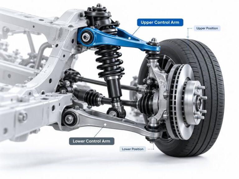
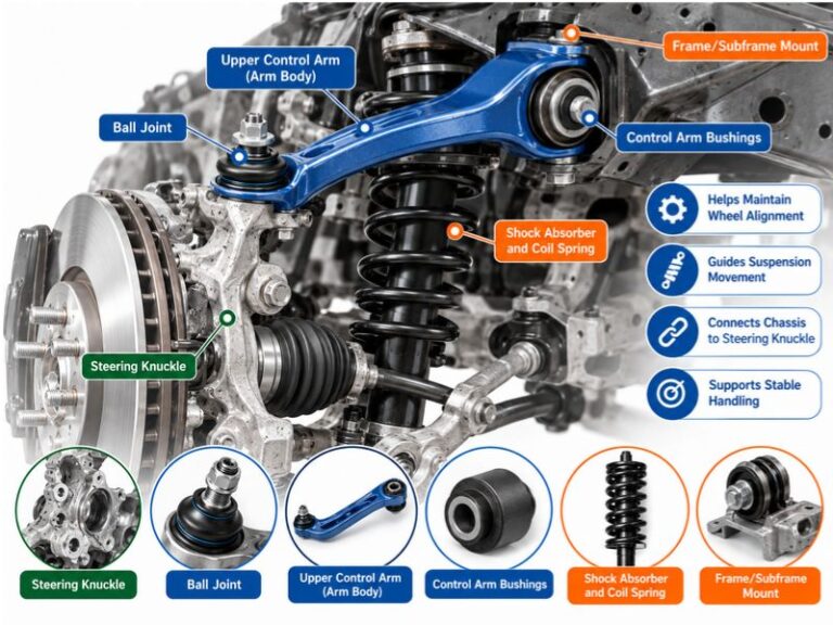
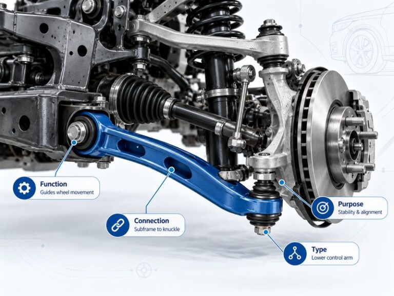
A worn front lower control arm can make an Infiniti G35 wander, clunk over bumps, or wear its tires unevenly. The arm connects the steering knuckle to the chassis, and its rubber bushings and ball joint control how the wheel moves. Once those parts are loose or cracked, the car may feel vague even when the rest of the suspension appears sound.
Replacing the arm is a realistic project for a careful home mechanic, but it is not a casual bolt-on job. The vehicle must be supported securely, the coil spring must remain undisturbed, and the final fasteners need to be tightened correctly. Model year, drivetrain, and replacement-part design can also change the exact hardware or procedure.
This guide explains how to replace lower control arm Infiniti G35 models using the front suspension as the reference. You will learn how to confirm the faulty part, remove the original arm without stressing the brake hose or axle, install the replacement, tighten bushing bolts at normal ride height, and check the result before arranging a wheel alignment.
At a glance
- Support the G35 by its chassis and let the suspension hang only after the spring and knuckle are safely controlled.
- Do not final-tighten pivot bushings with the suspension fully hanging; tighten them at normal ride height to avoid preloading the rubber.
- A control-arm replacement should be followed by a professional four-wheel alignment and a careful road test.
How to replace lower control arm Infiniti G35 safely
This procedure covers a front lower control arm on a typical G35. Confirm whether your car is rear-wheel drive or all-wheel drive, compare the replacement arm with the old one, and use the factory service information for your exact year before loosening anything. Some aftermarket arms include a new ball joint or bushings, while others require transferring or separately installing components.
Before starting, park on a firm, level surface and read the entire procedure. Keep the removed hardware organized by location; suspension bolts can look similar while having different lengths, shoulders, or locking features.
Tools you will need
- Floor jack and four appropriately rated jack stands for lifting and supporting the vehicle
- Wheel chocks to prevent movement
- Socket set, breaker bar, combination wrenches, and extensions that fit the suspension hardware
- Torque wrench capable of the fastener range listed in the factory service manual
- Ball-joint separator or suitable press equipment, only if the replacement arm does not include a ball joint
- Penetrating oil and a wire brush for corroded threads
- Replacement cotter pins and any specified one-time-use nuts or bolts
- Optional: paint marker, pry bar, and a second jack for supporting the steering knuckle

Step 1 Confirm the failed component and obtain the correct arm
Inspect the front suspension before buying parts. Look for a torn or separated control-arm bushing, a ball joint dust boot that is split or leaking grease, looseness when the wheel is lifted, or a clunk that changes when the brake is applied. A worn tie-rod end, sway-bar link, wheel bearing, or upper control arm can produce similar symptoms, so do not condemn the lower arm from noise alone.
Check the vehicle identification information and the side being repaired. Compare the new arm with the old one for mounting-hole layout, ball-joint position, bushing orientation, and left- or right-hand fit. If the new arm comes without a ball joint, verify that you have the correct press method and replacement joint before disassembly.
Important
Do not work under a vehicle supported only by a floor jack. If a ball joint or spring-related component is damaged, badly corroded, or unexpectedly loaded, stop and have a qualified technician take over rather than forcing it apart.
Step 2 Loosen the wheel hardware and raise the front safely
With the car on the ground, loosen the front wheel lug nuts slightly, but do not remove them. Place the transmission in Park or in gear, set the parking brake, and chock the rear wheels. If the parking brake operates on the rear wheels, it will not replace proper wheel chocks.
Lift the front of the G35 from an approved central point, then place jack stands under strong chassis or subframe support locations specified for the vehicle. Lower the car onto the stands, gently shake the body to confirm stability, and keep the jack lightly positioned as a backup only if it does not interfere with the work.
Remove the wheel and slide it under the chassis as an additional precaution. Never use a suspension arm or a thin floor pan as the sole support point unless the service information specifically identifies it.
Step 3 Support the steering knuckle and protect nearby parts
Before disconnecting the lower arm, place a second jack under the steering knuckle or another approved support point. Use only light support; the purpose is to prevent the knuckle from dropping or pulling on the brake hose, ABS sensor wire, or axle joint when the arm is released.
Inspect the brake hose and wheel-speed sensor wire where they pass near the control arm. If clips are attached to the arm, release them carefully and note their routing. Do not let the knuckle hang from a flexible brake hose, and do not stretch or twist the ABS wire.
On an all-wheel-drive model, take extra care around the front axle and related hardware. The general sequence is similar, but clearance and fastener arrangements may differ from a rear-wheel-drive G35.
Step 4 Remove the lower ball-joint connection
Clean exposed threads with a wire brush and apply penetrating oil if needed. Remove the cotter pin, if fitted, and loosen the ball-joint nut while keeping a few threads engaged until the taper is released. Replace a removed cotter pin rather than reusing it.
Separate the tapered ball-joint stud from the steering knuckle with a proper separator. A sharp release is normal, but uncontrolled hammering can damage the knuckle, wheel bearing, or nearby threads. If using a separator that bears against the stud, follow its instructions and protect the dust boot.
Once the taper is free, remove the nut and lower the knuckle only as far as the support allows. The ball joint should separate without forcing the brake hose or axle. If it will not release after reasonable pressure, stop and use the correct tool rather than heating or striking components near a bearing, sensor, or brake line.
Step 5 Unbolt the control arm from the chassis
Identify the control arm’s inner pivots and note how any washers, spacers, eccentric hardware, or brackets are positioned. Marking the original orientation can help during reassembly, although marks are not a substitute for an alignment.
Remove the inner pivot nuts and bolts while supporting the arm. A breaker bar may be necessary, but keep your hands clear of pinch points as the arm shifts. If a bolt is seized inside a bushing sleeve, do not repeatedly hammer against the subframe; cutting or professional extraction may be safer than damaging the mounting structure.
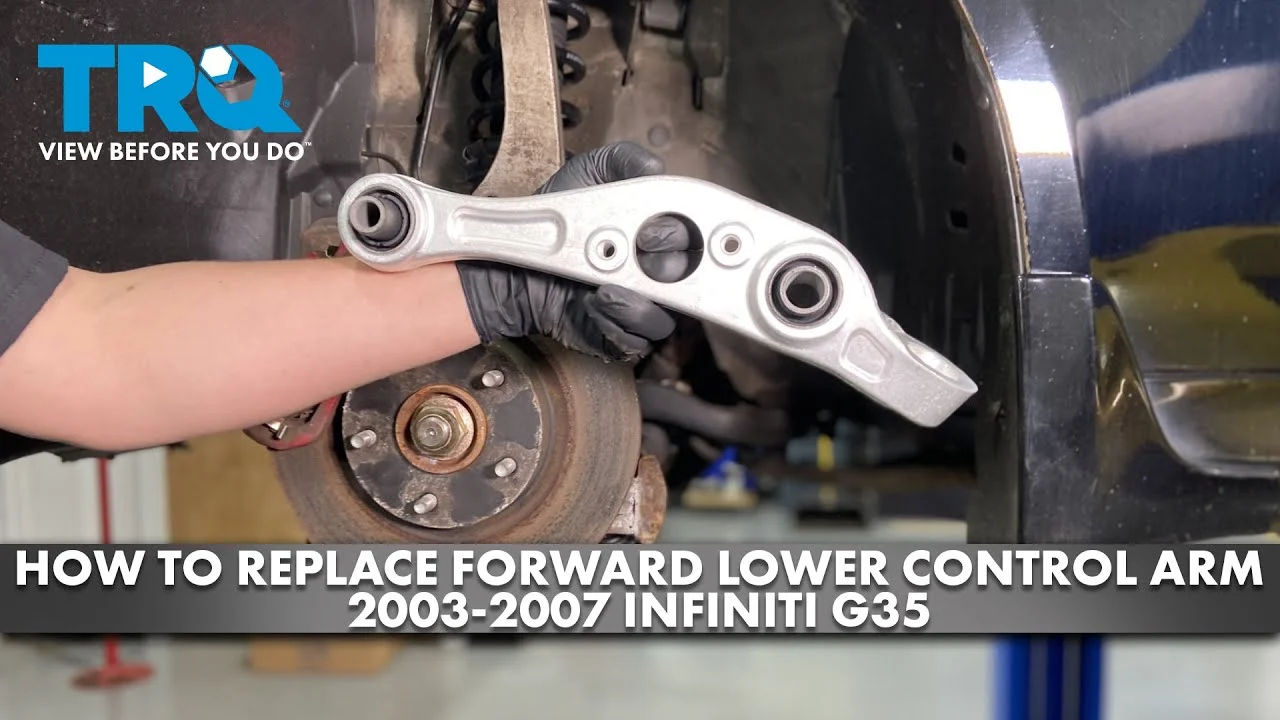
After the inner fasteners and ball-joint connection are free, remove the old arm. Compare it with the replacement again. The new part should sit naturally in the same position, with no need to bend the arm, enlarge holes, or force the ball-joint stud into alignment.
Step 6 Prepare and position the replacement arm
Inspect the replacement for shipping damage, correct bushing orientation, complete dust boots, and a properly seated ball joint. If the ball joint is supplied separately, install it with the specified press procedure and retaining hardware before putting the arm on the car. Do not improvise with a vise if the joint must be pressed squarely and you cannot control the force.
Position the arm in the chassis and install the inner bolts and nuts finger-tight. Reconnect the ball joint to the steering knuckle, ensuring the tapered stud is fully seated in its bore. Install the specified new locking nut or cotter pin arrangement, but do not guess at thread-locking products or reuse a prevailing-torque nut when the service information calls for a new one.
A useful way to approach how to replace lower control arm infiniti g35 is to check your progress after each stage.
Keep the arm supported while starting every fastener. If a bolt will not pass through easily, check alignment and bushing orientation; forcing it can cross-thread the nut or damage the new bushing.
Step 7 Tighten the joints in the correct suspension position
Snug the ball-joint hardware and inner pivot hardware, but do not final-tighten rubber-bushed pivots while the suspension hangs at full droop. That position twists the rubber when the car is lowered and can shorten bushing life or alter ride height.
Use a jack under the steering knuckle to raise the suspension to a realistic normal ride-height position. The exact reference is the angle specified by the service manual; the goal is to place the arm approximately where it sits with the vehicle resting on its tires, not to lift the chassis off the stands.
With the arm supported in that position, torque each fastener to the exact specification for your model and hardware. Tighten the ball-joint nut according to the specified procedure, then install a new cotter pin if the design uses one. Never align a castellated nut by loosening it; if the pin hole does not line up, follow the manual’s tightening range or replace the nut as directed.
Helpful tip
Write down the torque values from the correct factory service information before beginning. G35 suspension specifications vary by fastener and application, and a generic value is not a safe substitute.
Step 8 Reattach clips, reinstall the wheel, and lower the car
Restore the ABS wire and brake-hose clips exactly as they were routed. Turn the steering from side to side by hand and check that nothing rubs, binds, or becomes taut. Confirm that the ball-joint boot is not pinched and that the new arm does not contact the wheel or subframe.
Install the wheel and tighten the lug nuts in a crisscross pattern until snug. Raise the vehicle enough to remove the stands, lower it carefully, and torque the lug nuts to the vehicle’s specified wheel value. Do not use an impact gun as the final tightening method.
Step 9 Perform a stationary safety check before driving
With the G35 on level ground, compare the repaired side with the other side. The wheel should sit normally in the arch, the steering wheel should not be forced off-center, and there should be no visibly loose nut, missing cotter pin, disconnected clip, or leaking ball-joint boot.
Press the front corner down several times and listen for a sharp clunk or metal-to-metal contact. Start the engine, turn the steering slowly lock to lock without forcing it against the stops, and confirm that the brake hose and ABS wire remain clear. This check does not prove alignment or eliminate every suspension fault, but it can catch an obvious assembly problem before the road test.
Step 10 Road-test gently and arrange an alignment
Drive first at low speed in a quiet area. Apply the brakes lightly, pass over a small smooth bump, and listen for abnormal knocking. The steering should feel controlled, with no sudden pull, binding, vibration, or change in pedal feel.
If the car pulls sharply, the steering wheel is badly crooked, a wheel rubs, or any fastener moves, stop driving and recheck the installation. Once the short test is uneventful, have the front and rear alignment measured by a shop. Removing and installing a control arm can change toe or camber, and an alignment machine is the reliable way to verify the geometry rather than judging it by eye.
What the front lower control arm does
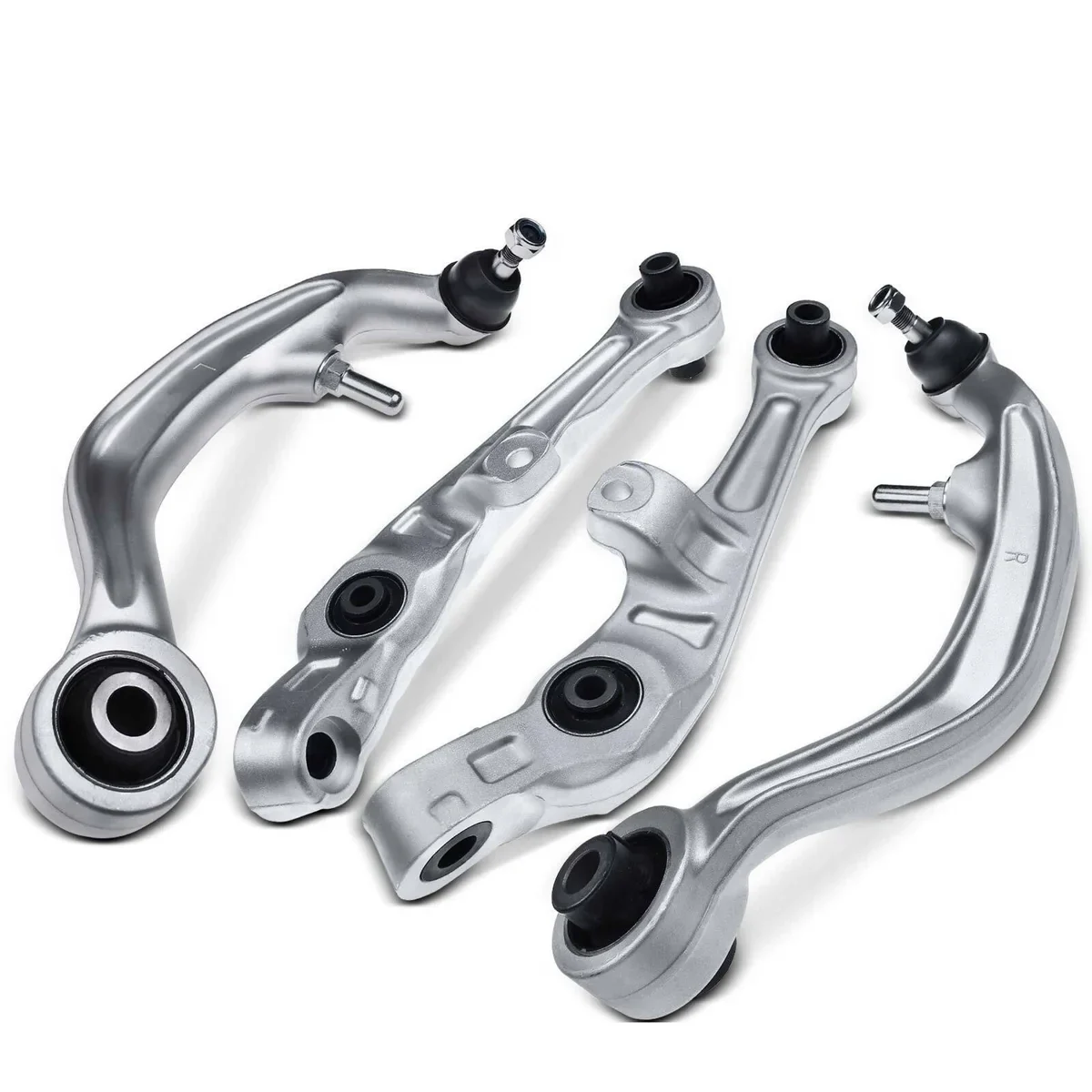
The lower control arm is a suspension link that locates the bottom of the steering knuckle while allowing the wheel to move up and down. Its inner bushings isolate road vibration and permit controlled movement, while the outer ball joint allows the knuckle to steer and articulate.
When people search for how to replace lower control arm Infiniti G35, they may be describing the complete arm, only a failed bushing, or a worn ball joint. Those are related but not identical repairs. Replacing the complete arm is often simpler when the arm is bent or both the bushing and joint are worn; pressing individual components can be appropriate when the arm itself is serviceable and the replacement parts are correct.
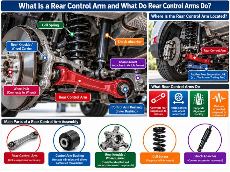
Do not confuse the front lower arm with the rear suspension’s lower links. A G35 also has several rear suspension arms, and their symptoms and removal procedures differ. Confirm the location before ordering parts or following a front-suspension procedure.
Signs that replacement is justified
- Visible separation, cracking, or excessive movement at a control-arm bushing.
- A damaged ball-joint boot accompanied by looseness or play at the joint.
- A clunk that remains after checking the sway-bar links, tie rods, wheel bearing, and brake hardware.
- Uneven tire wear or steering wander caused by suspension movement rather than incorrect tire pressure.
- A bent arm or shifted wheel position after a curb or pothole impact.
A visual inspection alone cannot always identify a worn ball joint. If you are unsure, have the front end checked with the wheel lifted and the suspension loaded or unloaded as appropriate for the suspected component.
How to verify the repair
A successful installation is more than a quiet first drive. Verification combines hardware checks, clearance checks, and alignment results. The arm should be secure, the wheel should move without binding, and the vehicle should track predictably after the alignment is corrected.
Use this final inspection checklist
- Every removed fastener is installed in its original location and tightened to the exact specification.
- Any required cotter pin, locking nut, or one-time-use fastener has been replaced as directed.
- The brake hose and ABS wire are clipped correctly and cannot touch the tire, spring, arm, or axle.
- The ball-joint dust boot is intact, seated, and not twisted or pinched.
- The wheel lug nuts are evenly tightened to specification.
- There is no contact through the steering range or during suspension movement.
- The alignment shop reports acceptable toe and camber readings rather than simply adjusting the steering wheel position.
Check your result
After the first short drive, park on level ground and look for shifted hardware, a torn boot, fresh grease, or a new gap at a bushing. Recheck lug-nut torque only with the vehicle safely stationary and follow the vehicle or wheel manufacturer’s guidance.
Common problems and safer alternatives
Corrosion is usually the part of this repair that changes the plan. Penetrating oil, cleaning exposed threads, and using the correct six-point socket may free ordinary hardware, but a seized pivot bolt can require cutting and replacement. If cutting is necessary near a brake hose, fuel line, wiring, or the subframe, professional help is the safer choice.
| Observation | Likely issue or next check |
|---|---|
| New clunk immediately after installation | Loose hardware, a mis-seated ball-joint taper, damaged sway-bar link, or incorrect bushing preload; stop and inspect before driving farther. |
| Steering wheel is off-center or the car pulls | Alignment changed, tire pressure differs, or another bent component is present; obtain an alignment and suspension inspection. |
| Ball-joint stud spins while tightening | The taper may not be seated, or the stud’s holding feature is not engaged; support the knuckle correctly and follow the specified installation method. |
| Pivot bolt will not slide out | The sleeve may be seized to the bolt. Avoid damaging the subframe; use the proper extraction method or seek a repair shop. |
When pressing a bushing or ball joint is the better option
If the control arm is straight and the manufacturer supplies serviceable bushings or a separate ball joint, pressing individual parts can reduce unnecessary replacement. It requires a press, correct adapters, and accurate orientation marks. A joint pressed in crooked can fail prematurely or damage the arm, so a complete assembled arm is the more practical option for many beginners.
When to stop the repair
Stop if the car cannot be supported securely, the coil spring or knuckle is damaged, a mounting point is cracked, or you cannot identify the correct fastener specifications. Also stop if the replacement part does not match the original or if a brake hose, ABS wire, axle, or wheel bearing was damaged during removal. A suspension failure can affect steering control, so uncertainty is a valid reason to use a qualified shop.
Frequently asked questions
Can I replace only the lower control arm bushing?
Yes, if the arm is straight and the bushing is available separately, but it normally requires proper press equipment and orientation. Replacing the complete arm is often simpler when the ball joint is also worn or the old arm is corroded.
Do I need to replace both lower control arms?
Not automatically. Replace the damaged side after confirming the diagnosis, then inspect the opposite side for matching wear, cracked bushings, or looseness. Replacing both sides can provide more even suspension performance when both have similar mileage, but it is not a substitute for inspection.
Can I drive without an alignment after the repair?
Drive only as far as necessary for a cautious initial check if the steering feels normal and no hardware problem is visible. Schedule an alignment promptly because control-arm removal can alter suspension geometry and cause rapid tire wear.
Should the control-arm bolts be tightened with the car on the ground?
The important point is normal ride-height suspension position, not simply whether the tires touch the ground. If access allows, the car can be on ramps or an approved lift setup; otherwise, support the arm or knuckle at the specified ride-height position before final-tightening rubber-bushed pivots.
Why is the steering wheel crooked after replacing the arm?
The arm may have changed toe or camber, or another suspension component may be bent. Have the alignment measured rather than trying to correct the steering wheel by moving parts at random.
Does a new control arm fix every front-end clunk?
No. Sway-bar links, tie-rod ends, upper control arms, strut mounts, wheel bearings, and loose brake hardware can sound similar. If the noise remains, inspect the entire front suspension instead of repeatedly replacing control arms.
Finish the repair with a measured check
Learning how to replace lower control arm Infiniti G35 models safely comes down to controlled disassembly, correct support, accurate fastener tightening, and verification after the car is back on its wheels. Match the replacement part carefully, protect the brake and ABS components, and never final-tighten rubber bushings at full suspension droop.
After the initial road test, arrange a professional alignment and respond to any pull, vibration, new noise, or visible looseness. If corrosion, damaged mounting points, or spring and ball-joint problems make the job uncertain, stopping early is the safest successful outcome.