
How to Install Coilover Conversion Kit Safely on Your Vehicle
Replacing a factory air suspension or worn spring-and-shock assembly with a coilover conversion kit can make a vehicle easier to maintain, but the job is more than swapping one shock for another. The springs carry the vehicle’s weight, the dampers control its motion, and every mounting point must remain correctly aligned. A mistake at any of those points can affect steering, braking, tire wear, and stability.
This guide explains how to install coilover conversion kit components on a typical passenger vehicle while allowing for the differences between cars, trucks, front struts, rear shocks, and air-to-coil conversions. The kit’s vehicle-specific instructions always take priority because mounting hardware, spring rates, ride-height ranges, and electronic components vary.
You will learn how to confirm compatibility, support the vehicle safely, remove the original suspension, assemble and install the new units, set a sensible ride height, and check the result before driving normally. If a fastener, spring seat, mounting point, or electrical warning is unclear, stop rather than guessing; a qualified suspension technician is the safer next step.
At a glance
- Confirm the kit matches the exact vehicle, suspension layout, load rating, and intended ride height.
- Support the vehicle with approved jack stands and control compressed springs with the correct equipment.
- Finish with a torque check, wheel alignment, clearance inspection, and cautious road test.
How to install coilover conversion kit components safely
A coilover conversion kit normally combines a damper, a coil spring, spring seats, and vehicle-specific brackets or mounting hardware. Some kits replace air springs and retain the original shocks; others replace complete strut assemblies. Before removing anything, identify which design you have and compare every part with the instructions and the vehicle.
Tools you will need
- Vehicle-specific coilover conversion kit and installation instructions, including all brackets, isolators, spacers, and fasteners
- Floor jack and four appropriately rated jack stands for lifting and supporting the vehicle
- Wheel chocks to prevent movement while one axle is raised
- Socket and wrench set, breaker bar, and penetrating oil for suspension fasteners
- Calibrated torque wrench for final tightening
- Spring compressor approved for the spring and assembly, if the kit requires spring assembly or reuse of a factory spring
- Measuring tape or ride-height gauge to compare both sides
- Safety glasses, gloves, and a paint marker for marking positions before removal
- Optional: trim tools, a scan tool, or an electronic suspension module recommended by the kit manufacturer
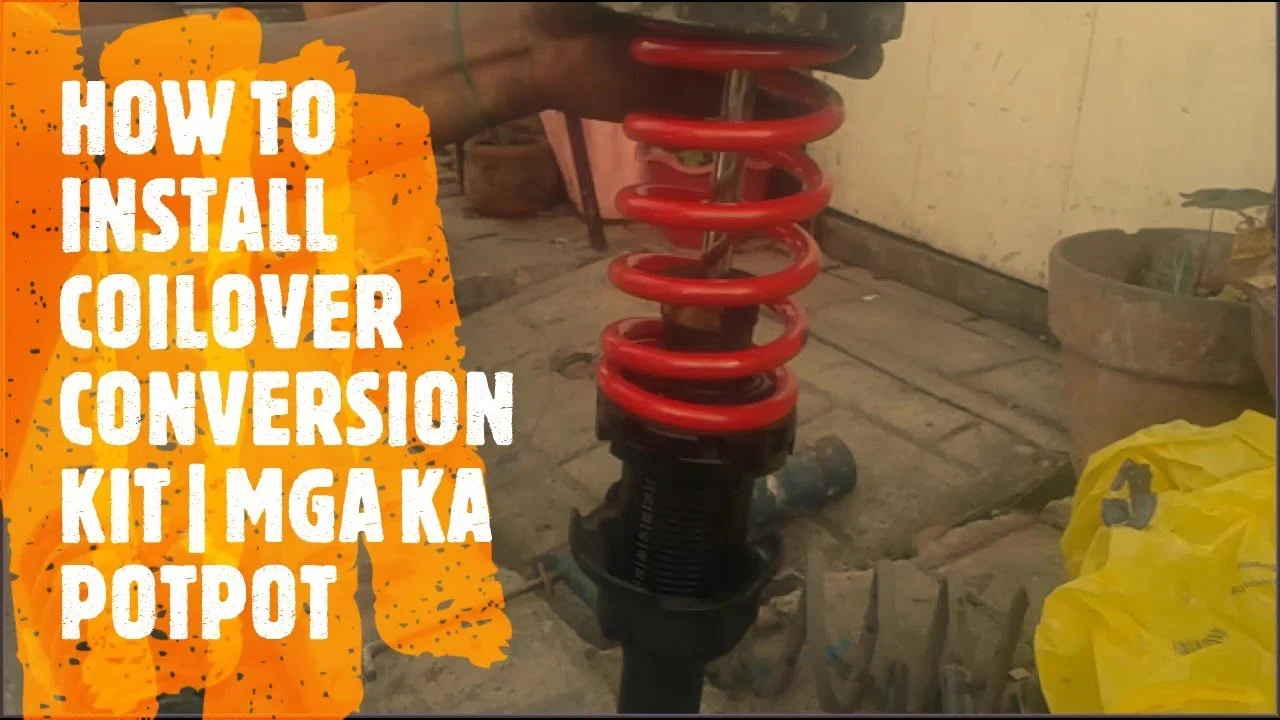
Step 1 Confirm compatibility and inspect the kit
Read the kit instructions from beginning to end before lifting the vehicle. Verify the exact model year, body style, drivetrain, axle configuration, brake package, and suspension option. A kit made for a similar-looking vehicle may use different strut lengths, mounting holes, spring rates, or brake-line brackets.
Lay out the left- and right-hand components and compare them with the parts list. Look for the correct springs, top mounts, lower brackets, spacers, bump stops, dust boots, isolators, retaining hardware, and any air-line plugs or electronic modules. Do not substitute random bolts or omit a spacer because the assembly appears to fit without it.
Inspect the vehicle for rust, cracked mounting metal, bent control arms, leaking dampers, damaged brake hoses, and worn ball joints. A conversion kit cannot correct a weakened chassis or a failed steering component. Photograph the original hose routing and bracket locations so replacement parts can be positioned without rubbing.
Step 2 Measure the existing ride height and prepare the work area
Park on a level, hard surface and record the current ride height before disassembly. Measure from the center of each wheel hub vertically to the lower edge of the fender, or use the measurement method specified by the kit. Record all four corners and note whether the vehicle is carrying unusual cargo or fuel.
Place the transmission in Park or in first gear for a manual transmission, apply the parking brake, and chock the wheels that will remain on the ground. Loosen the wheel lug nuts slightly before lifting, but do not remove them while the vehicle is supported only by the jack.
Check that the floor jack and stands can reach the manufacturer-approved lifting and support points. Keep the stands on level ground, and never rely on the jack as the only support. Once the vehicle is raised, gently test its stability before placing any part of your body underneath it.
Important
Never loosen a pressurized air-suspension component or remove a spring that is still carrying vehicle weight unless the kit instructions give a safe release procedure. Pressurized air and compressed springs can release energy suddenly; use the manufacturer’s procedure or qualified help.
Step 3 Disable the original suspension system as directed
Air-to-coil conversions commonly require the air suspension to be depressurized and its compressor or control system to be disabled. Follow the kit instructions and the vehicle service information for fuse removal, electrical connectors, air-line release, and warning-light handling. Do not cut an air line while it is pressurized, and do not unplug connectors by pulling on their wires.
Some vehicles need a supplied electronic bypass module or a software configuration to prevent a suspension warning. Other kits intentionally leave the original module active. Use only the method specified for your vehicle; an unapproved resistor or improvised wiring can create faults or conceal a real problem.
After the system is disabled, confirm that the vehicle is fully supported and that the original suspension is no longer holding pressure or load. Cap or secure open air lines as directed so dirt and moisture do not enter components that remain in service.
Step 4 Remove the wheel and document the original assembly
Raise the axle according to the vehicle’s lifting instructions, position the jack stands, and remove the wheels. Keep the lug nuts together and place the wheels where they cannot roll into the work area.
Before disconnecting anything, use a paint marker to identify the location of adjustable links, eccentric washers, and brackets if the design uses them. Marking is not a substitute for alignment, but it helps you return hardware to its approximate original position.
Photograph the brake hose, ABS wire, sway-bar link, and ride-height sensor routing. These parts must not be trapped between the coilover and the tire or stretched when the suspension moves. Support a brake caliper with wire if it must be removed; never let it hang from the flexible hose.
Step 5 Remove the factory spring, shock, or strut safely
Remove the hardware that connects the original damper or strut to the knuckle, control arm, and body, following the order in the instructions. Support the hub or control arm with a second jack when removing a bolt that controls suspension height. This prevents the assembly from dropping or shifting unexpectedly.
If the original design uses a separate coil spring, unload it only with the correct spring compressor or the vehicle-specific procedure. A spring that is visibly loose is not automatically safe; it may still be compressed between its seats. If you do not have a suitable compressor or cannot identify the safe loading points, stop and have the assembly handled by a suspension shop.
For a complete strut assembly, remove the upper mounting nuts only after the lower assembly is supported. Keep track of the order and orientation of washers, rubber isolators, and bearing plates. The top mount may look symmetrical while still requiring a specific direction.
A useful way to approach how to install coilover conversion kit is to check your progress after each stage.
On a rear suspension, the spring and damper may be separate. Do not assume the front installation method applies to the rear. Some conversion kits use a coilover in one location and a separate spring seat in another, so follow the diagrams for each axle.
Step 6 Assemble the coilover units in the specified order
Place the new parts on a clean surface and compare the assembly order with the kit diagram. A typical unit may include a lower mount, threaded body, adjustment collar, spring, upper spring seat, dust boot, bump stop, top hat, bearing, and retaining nut. The exact order differs, especially when the kit reuses an original top mount.
Before compressing a spring, make sure the spring compressor is designed for its diameter and length and that both hooks are fully engaged. Tighten it evenly, keep your hands away from the spring’s path, and position the assembly so it cannot roll. Do not use improvised clamps, wire, or a cargo strap as a spring compressor.
Set the initial threaded-body or spring-seat position to the measurement in the instructions. If no starting measurement is supplied, use the manufacturer’s neutral setting rather than lowering the vehicle as far as possible. Excessive lowering can reduce bump travel, cause tire contact, and place the driveshaft or control arms at an unfavorable angle.
Make sure the spring ends sit against the shaped pockets in both seats. A spring that is not seated can rotate, snap into position, or change the ride height after installation. The finished assembly should match the left and right orientation shown in the instructions.
Step 7 Install the new suspension assemblies
Lift each coilover into position without forcing the mounting holes into alignment. Install the upper hardware finger-tight first, then attach the lower mount and any supplied spacers or brackets. If a bolt will not pass through easily, lower or raise the supporting jack slightly rather than driving the bolt through with a hammer.
Route the brake hose and ABS wire through the supplied brackets and compare their position at normal ride height and full steering lock. They should have slack through the suspension’s movement, remain clear of the spring and tire, and avoid sharp edges. Reinstall sway-bar links, ride-height sensors, and other attachments in their original or kit-specified locations.
For a conversion that retains separate rear springs, place each spring’s isolator in the correct upper and lower seat before raising the suspension into place. Confirm that the pigtail end of the spring points in the specified direction. A missing rubber isolator can create noise and alter the installed height.
Step 8 Snug the hardware and torque it at the correct suspension position
Snug all fasteners while the suspension is supported, but do not fully tighten rubber-bushed pivot bolts while the wheels are hanging. Those bushings are designed to operate near normal ride height; tightening them at full droop can preload the rubber and shorten its life.
Use the kit and vehicle service specifications for every fastener. Tighten in stages with a calibrated torque wrench, and use new prevailing-torque nuts or single-use bolts when specified. A torque wrench is not a breaker bar, so loosen seized hardware with the breaker bar and perform final tightening separately.
After torqueing, mark the fastener and adjacent metal with a paint marker if the instructions recommend a visual witness mark. This makes a later inspection easier. Verify that no tool, spring compressor, shipping spacer, or temporary transport clip remains in the assembly.
Step 9 Reinstall the wheels and set a conservative initial height
Reinstall the wheels and tighten the lug nuts by hand. Lower the vehicle until the tires touch the ground, then tighten the lug nuts in a star pattern to the vehicle’s specified torque. Fully lower the vehicle and remove the chocks only when the work area is clear.
Roll the vehicle forward and backward a short distance on level ground, or gently bounce each corner if the kit instructions permit it. This allows the suspension to settle. Measure hub center to fender on both sides and compare the results with the intended starting height.
Adjust ride height in small, equal changes from side to side. Use the permitted adjustment method: some coilovers require turning a spring perch, while others use a threaded lower body so spring preload is preserved. Do not create a large height difference to compensate for a worn spring, bent component, or uneven surface.
Step 10 Perform the initial clearance and function check
With the vehicle on the ground, turn the steering from lock to lock and inspect the tire, spring, brake hose, ABS wire, and damper body. If possible, repeat the inspection with the suspension at full droop and with the wheel raised carefully to approximate compression. The tire must not contact the spring, body, liner, or brake components.
Check that the coilover does not bind as the steering moves and that the spring remains seated. Inspect the top mounts, lower brackets, control arms, and sway-bar links for contact. Listen for a spring that shifts, a metal-on-metal knock, or a hose that pulls tight.
Understanding how to install coilover conversion kit also means recognizing the limits of the method.
Check your result
A successful stationary check shows equal side-to-side installation, seated springs, secure brake and ABS routing, no tire contact, and no loose or missing hardware. Any contact, binding, or sudden height change requires correction before driving.
Step 11 Complete alignment and the controlled road test
Any suspension conversion or ride-height change can alter toe, camber, and caster. Drive only far enough to reach a safe testing location or alignment facility, and arrange a professional four-wheel alignment before normal driving. Tell the technician that the suspension has been converted and provide the intended ride height.
For the first short test, use a low-speed route with little traffic. Listen for clunks, rubbing, popping, or repeated tire contact, and notice whether the vehicle pulls, wanders, sits unevenly, or feels unusually harsh. Test the brakes gently and avoid aggressive cornering, high speed, and rough roads until the inspection is complete.
After the test, recheck the ride height and inspect every accessible fastener and hose. Some kits require a re-torque after initial settling, so follow that instruction. Do not continue driving if a warning light appears with other symptoms, the vehicle pulls sharply, a tire rubs, or a suspension corner drops.
What changes when an air suspension is converted?
An air suspension uses air pressure to support the vehicle, while a coilover conversion uses a steel coil spring and a damper. The conversion removes the need for air bags, compressor operation, and some electronic controls, but it also changes the vehicle’s load response and may change its original self-leveling behavior.
Spring rate determines how much the suspension resists compression. Damper adjustment controls how quickly the suspension moves, but a damper setting cannot compensate for an incorrect spring rate or insufficient suspension travel. Ride height also affects alignment angles, bump-stop engagement, and available clearance.

Front strut conversions versus separate shock and spring systems
On a MacPherson-strut front suspension, the strut helps locate the steering knuckle, so its length and upper bearing orientation matter. On a separate shock-and-spring layout, the shock may control motion without carrying the spring’s full side load. The installation procedure and the consequences of a wrong part are therefore different.
Read the kit diagram for each axle rather than treating all four corners as identical. Left and right parts may be mirror images, and a rear conversion may include a height-adjustable spring perch instead of a complete coilover body.
Electronic suspension warnings
Removing air springs or unplugging ride-height sensors can trigger a warning message. Whether that warning can be cleared, must be electronically coded out, or should remain active depends on the vehicle and kit.
Do not disable unrelated warning systems to hide a problem. If the vehicle has adaptive dampers, active leveling, or interconnected control modules, use the kit’s approved integration method and verify that steering, braking, and stability-control systems remain free of faults.
How to verify the finished installation
The installation is not complete when the vehicle first sits on its wheels. Verification confirms that the suspension moves freely, the vehicle is aligned, and the new ride height does not create a safety problem.

- Compare left and right ride height on a level surface after the vehicle has settled.
- Confirm that wheel lug nuts and suspension fasteners are tightened to their specified values.
- Check tire clearance through steering movement and available suspension travel.
- Inspect brake hoses, ABS wiring, and height-sensor links for tension, twisting, or rubbing.
- Look for leaking fluid, damaged threads, loose collars, displaced springs, or missing isolators.
- Obtain a four-wheel alignment and keep the alignment report for reference.
- Reinspect after the first short drive and again after the kit’s recommended settling or re-torque interval.
A proper alignment report should show values within the vehicle or kit’s acceptable range, not merely a steering wheel that appears centered. Uneven camber, excessive toe, or a vehicle that pulls can indicate an installation issue, worn component, or ride height outside the usable range.
Common problems after a coilover conversion
Most post-installation symptoms have a physical cause that can be found with a careful inspection. Do not turn adjustment collars repeatedly without first determining whether the problem is installation, alignment, clearance, or a worn component.
| Symptom | Likely checks |
|---|---|
| Clunk or pop over bumps | Check loose upper or lower hardware, a displaced spring, sway-bar links, top-mount orientation, and contact between components. |
| Vehicle pulls or steering wheel is off-center | Verify tire pressures, ride-height equality, alignment, and whether a brake or suspension part is binding. |
| Tire or spring rubs | Inspect ride height, wheel offset, spring position, brake-line routing, steering-lock clearance, and available bump travel. |
| One corner sits lower | Check spring seating, adjustment-collar position, incorrect left/right parts, worn components, and the measurement surface. |
| Harsh ride or frequent bottoming | Check damper and spring settings, bump-stop length, ride height, load, and whether the kit is appropriate for the vehicle. |
When to stop troubleshooting at home
Stop and seek qualified help if a spring will not seat, a mounting hole is misaligned, a bracket is cracked or bent, a brake hose is damaged, or a fastener spins without tightening. The same applies if the vehicle drops suddenly, the suspension binds, or you cannot verify the torque specification.
Suspension work becomes especially risky when rust has weakened a mounting point or when the vehicle has electronically controlled steering, braking, or stability systems. A professional inspection is less costly than testing an uncertain repair on public roads.
Beginner questions about coilover conversion kits
Can I install a coilover conversion kit without a spring compressor?
Only if the kit arrives as a complete, preassembled unit or its instructions specifically avoid spring assembly. If a separate spring must be installed on a strut or coilover body, use an approved compressor or have that portion assembled by a qualified shop.
Does a coilover conversion automatically lower the vehicle?
No. Many kits allow height adjustment, but the starting height should follow the manufacturer’s range and preserve adequate bump travel and clearance. Lowering farther than recommended can create rubbing, poor alignment, and bottoming.
Do I need an alignment after the conversion?
Yes. Removing or replacing suspension components can change toe, camber, and caster even when the vehicle appears to sit at its original height. Arrange a four-wheel alignment before regular driving.
Why does the vehicle have a suspension warning after installation?
The original control module may detect missing air-pressure components, unplugged sensors, or removed dampers. Use the kit’s approved electronic solution and scan for faults; do not assume every warning can be safely ignored.
Can I reuse the original suspension hardware?
Reuse it only when the kit instructions specifically call for it and the hardware is undamaged. Replace single-use bolts, prevailing-torque nuts, worn isolators, and corroded fasteners as directed by the vehicle or kit documentation.
Finish the conversion with verification, not just installation
Learning how to install coilover conversion kit components means more than attaching new springs and dampers. The safe result is a correctly matched kit with seated springs, properly torqued mounts, protected brake and ABS routing, usable ride height, adequate clearance, and a professional alignment.
Once the first inspection and cautious road test are complete, monitor the vehicle for noise, rubbing, uneven height, warning lights, and changes in handling. If any part of the installation remains uncertain, stop driving and have the suspension checked before making further adjustments.


